• Skip to main content
  • Skip to primary sidebar

Homemade Circuit Projects

Need circuit help? Post them in the comments! I've answered over 50,000!

Blog | Categories | About | Contact | Calculators-online
You are here: Home / Power Supply Circuits / Cheapest SMPS Circuit Using MJE13005

DIY Circuits | Learn Basics | Arduino Coding


Cheapest SMPS Circuit Using MJE13005

Last Updated on January 8, 2024 by Swagatam 61 Comments

The explained circuit in this article is probably the simplest and the cheapest, since it employs minimum number of components and the making of the circuit is very straightforward.

Circuit Operation

Generally SMPS topology involves some fixed standard stages and criteria. Thgey may be listed in the following manner:

The first stage which is the input stage incorporates an obvious mains rectifiers stage, followed a few important protection components.

The above protection components may be in the form of an MOV , or an NTC or both of these for suppressing high voltage transients.

The next stage involves a mosfet based IC in conjunction with the primary of a small transformer for generating the required oscillations.

The IC is normally a state-of -the-art chip having many in built features and abilities.

Further on the secondary of the transformer is clamped with the mosfet IC through a optocoupler which takes the responsibility of controlling the output voltage to a predetermined fixed level.

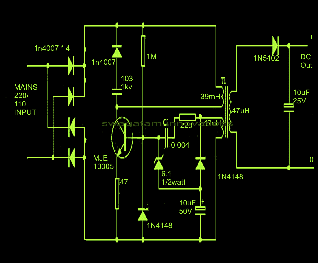
However the proposed circuit of a cheapest SMPS circuit is rather free from all these complications and employs a very simple configuration.

The input does not involve any protection, which is rather replaced with the snubber network around the transistor. Moreover the rugged MJE13055 is assumably strong enough to take on most the situations.

The two winding on the primary side are so arranged that on switch ON the circuit immediately starts oscillating at around 100 kHz.
The secondary winding typically decides the output voltage and here no optos or zeners are introduced for the sake of simplicity.

Having said that, the circuit  may be considered quite crude and therefore in some way might be vulnerable at some point of time in the long run.

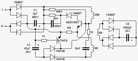
Here's another identical  simple 220V SMPS circuit design you would like to investigate:

You'll also like:

  • smps2B3002Bwatt2Baudio2Bamp2Bpower2Bsupply2BcircuitSMPS 2 x 50V 350W Circuit for Audio Power Amplifiers
  • simple short circuit protection for power suppllies using relayAdd this Short Circuit Protection to Your Power Supply
  • ZEROTO220300VVARIABLEPOWERSUPPLYCIRCUIT0-300V Adjustable Transformerless Power Supply Circuit Diagram
  • lm196 pinout details15V 10 Amp Voltage Regulator Circuit Using IC LM196

Filed Under: Power Supply Circuits Tagged With: Cheapest, MJE13005, SMPS

About Swagatam

I am an electronics engineer and doing practical hands-on work from more than 15 years now. Building real circuits, testing them and also making PCB layouts by myself. I really love doing all these things like inventing something new, designing electronics and also helping other people like hobby guys who want to make their own cool circuits at home.

And that is the main reason why I started this website homemade-circuits.com, to share different types of circuit ideas..

If you are having any kind of doubt or question related to circuits then just write down your question in the comment box below, I am like always checking, so I guarantee I will reply you for sure!

Previous Post: « Low Battery and Overload Protection Circuit for Inverters
Next Post: Basics of Strain Gauge Measurements »

Reader Interactions

Comments

khem cabuga says:
May 2, 2015 at 3:05 am

Hello sir,

I hav noticed the 2nd schema, that it has a bridge rectifier both in input and output, it is in wrong configuration, and also in the collector of the transistor, the diode is reversed biased. Therefore this circuit wont work,

Sorry, just trying to help.

Reply
sudhir hora says:
March 9, 2015 at 5:48 pm

Hi,regards.i m designing a 5v 1amp smps can u pls help me to get some idea.i want to charge samsung phone.i opened a samsung charger it consist of 13003 transistor and one 5 pin smd very small part to drive 13003.it marked rf27.in another charger it marked in30 and another one marked in70.can u pls help me to make a fast charger

Reply
Swagatam says:
March 10, 2015 at 11:48 am

Hi, I could not find any info regarding the devices in30, in70, so can't suggest much, rather you could try the following design for getting identical results:

https://www.homemade-circuits.com/2014/02/220v-smps-cell-phone-charger-circuit.html

Reply
KHODAL DHAM says:
June 20, 2014 at 5:37 pm

sir i want 24 volt 1 amp ckt in above ckt some suggestion plz..
thnks

Reply
Swagatam says:
June 21, 2014 at 5:35 am

Khodal, the above designs are not confirmed ones, instead you can try the following , but you will need to make a PCB for this:

https://www.homemade-circuits.com/2013/10/12v-24v-1-amp-mosfet-smps-circuit.html

Reply
Souvik Patra says:
April 3, 2014 at 6:45 am

can you explain the working please… i thought that the reservoir cap shud be between the ground and vcc of the primary.(hi voltage section i mean).. but here its btween the vcc and the transistor… :/

Reply
Swagatam says:
April 4, 2014 at 7:33 am

a filter capacitor may be added after the bridge, the capacitor you are referring to has a different function and is also crucial.

Reply
Arshad pc says:
December 9, 2013 at 8:01 am

don't use 1N series at the output such diodes used for Low frequency rectification….u have to use fast recovery diode like UF5402(ultra fast diodes)…switching frequency of smps is in terms of kHz..mail me if you want efficient and cheap smps circuit design using BJT and mosfets..arspc8@gmail.com

Reply
Abubaker Naseer says:
September 20, 2013 at 6:23 am

In this circuit Please tell me which Component you used for high frequency switching?

Reply
Swagatam says:
September 20, 2013 at 12:29 pm

the transistor and the associated components.

Reply
Swagatam says:
August 8, 2013 at 3:59 pm

Hi Kumar,
I am sorry, I don't have the exact specifications for the transformer

Reply
Back to Newest

Need Help? Please Leave a Comment! We value your input—Kindly keep it relevant to the above topic! Cancel reply

Your email address will not be published. Required fields are marked *

Primary Sidebar

circuit simulator image


Subscribe to get New Circuits in your Email


Categories

  • Arduino Projects (93)
  • Audio and Amplifier Projects (133)
  • Automation Projects (17)
  • Automobile Electronics (101)
  • Battery Charger Circuits (85)
  • Datasheets and Components (109)
  • Electronics Theory (149)
  • Energy from Magnets (27)
  • Games and Sports Projects (11)
  • Grid and 3-Phase (20)
  • Health related Projects (27)
  • Home Electrical Circuits (13)
  • Indicator Circuits (16)
  • Inverter Circuits (95)
  • Lamps and Lights (159)
  • Meters and Testers (71)
  • Mini Projects (28)
  • Motor Controller (68)
  • Oscillator Circuits (28)
  • Pets and Pests (15)
  • Power Supply Circuits (91)
  • Remote Control Circuits (50)
  • Renewable Energy (12)
  • Security and Alarm (64)
  • Sensors and Detectors (106)
  • SMPS and Converters (34)
  • Solar Controller Circuits (60)
  • Temperature Controllers (43)
  • Timer and Delay Relay (49)
  • Voltage Control and Protection (42)
  • Water Controller (36)
  • Wireless Circuits (30)


Other Links

  • Privacy Policy
  • Cookie Policy
  • Disclaimer
  • Copyright
  • Videos
  • Sitemap


People also Search

555 Circuits | 741 Circuits | LM324 Circuits | LM338 Circuits | 4017 Circuits | Ultrasonic Projects | SMPS Projects | Christmas Projects | MOSFETs | Radio Circuits | Laser Circuits | PIR Projects |

Social Profiles

  • Twitter
  • YouTube
  • Instagram
  • Pinterest
  • My Facebook-Page
  • Stack Exchange
  • Linkedin


Recent Comments

  • Swagatam on 7 Best Touch Sensor Switch Circuits Explored
  • Swagatam on Tuned Radio Frequency (TRF) Receiver Circuits
  • Swagatam on Automatic Street Light Dimmer Circuit
  • Swagatam on Electronic Circuit Projects, Tutorials, and Practical Engineering Solutions
  • Ghulam Mohio Din on Automatic Street Light Dimmer Circuit

© 2026 · Swagatam Innovations