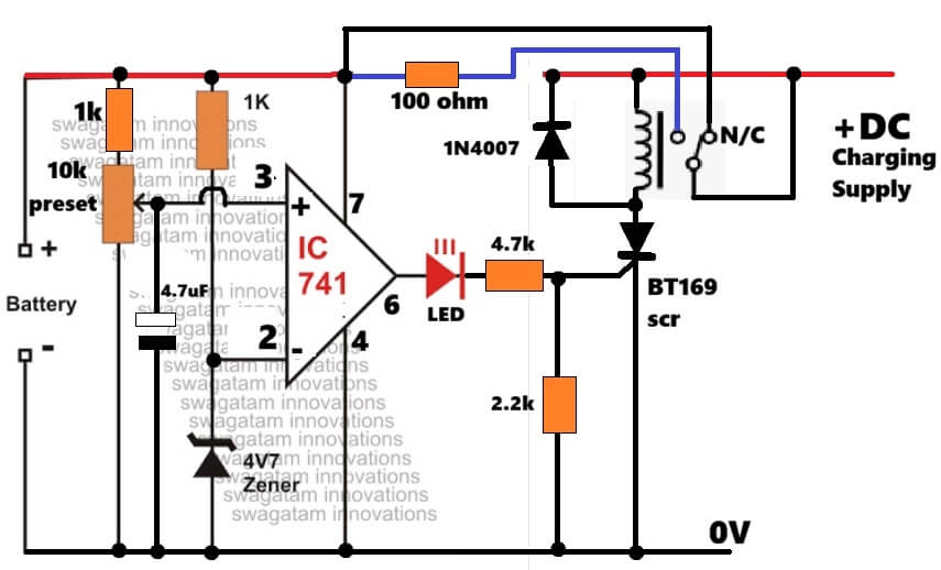
In this post I will explain one useful SCR relay battery overcharge cut off circuit, which also has automatic latching and small trickle charging feature, so now when battery becomes fully charged then charger disconnects automatically, but still a tiny current keeps going into battery slowly. Main Features Main interesting thing here is the SCR […]
Newly Updated Circuit Projects:
How to Connect Car LED Downlight: Circuit Diagram
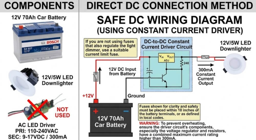
A car LED downlight available in the market can be easily integrated to an existing car battery if its rating is identical to the battery’s voltage rating. I have explained more regarding one such request sent by Mr. Allwyn Siqueira. How to Connect Downlight to 12V Car Battery Hi Swagatam, I’ve just spent the last […]
Fence Charger Animal Contact Detector Circuit with Audible Buzzer
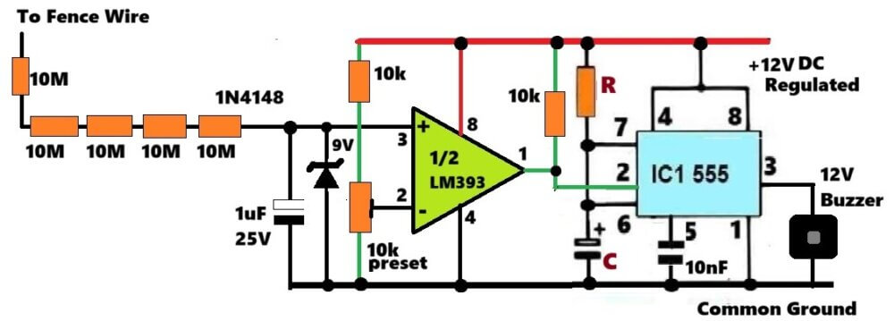
In one of my electric fence charger articles, one reader asked me something interesting. He wanted to know whether a buzzer could be made to sound whenever an animal touches the fence. At first I was thinking about a current sensing method because that looks like the obvious way. But after looking at how electric […]
Simple AM Radio Receiver using IC TA7642
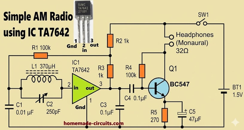
We see this radio circuit is very basic, not too many parts, but still it works. This circuit shows how a full MW radio can be made with very few parts. The main part is TA7642 which already has RF amplifier, detector, AGC inside, so we do not need to build all that outside. Main […]
How to Upgrade EGS002 Inverter to 5kVA Level
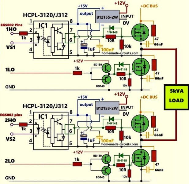
In this article I will explain how to upgrade an EGS002 inverter board to 5kVA power level using the HCPL-3120 or HCPL-J312 opto isolated drivers with isolated inputs and isolated power supply stages. However, the low side MOSFETs are driven through ordinary BJT totem pole configuration such as by using BD139 and BD140 transistor pairs. […]
3 Glittering LED Christmas Tree Light Circuits Explored
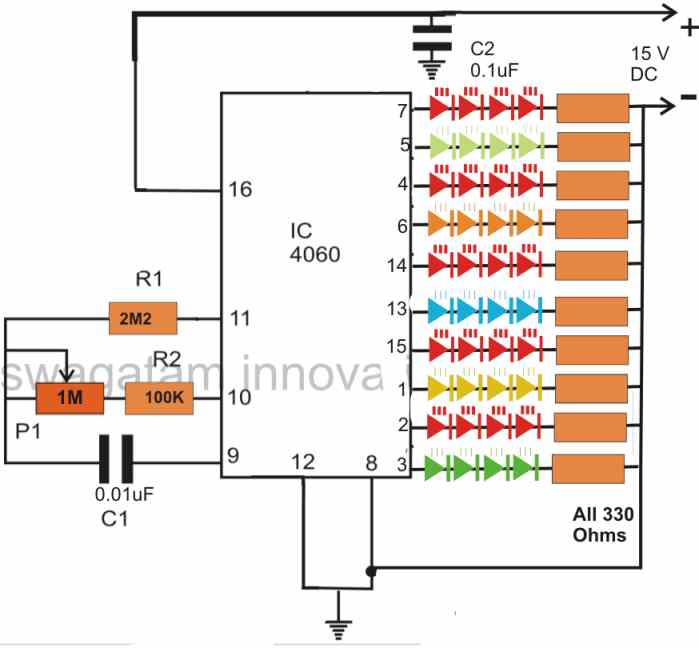
In this post we present 3 circuit ideas for creating beautiful Christmas tree light decorations. The first idea explains a transistorized flashing blinking LED string light which can be mounted on a Christmas tree. The second circuit diagram describes an LED light effect generator which can be also installed over a real Christmas tree for […]