• Skip to main content
  • Skip to primary sidebar

Homemade Circuit Projects

Need circuit help? Post them in the comments! I've answered over 50,000!

Blog | Categories | About | Contact | Calculators-online
You are here: Home / Arduino Projects / Blinking an LED with Delay – Arduino Basics

Circuit Simulator: Assemble and Simulate

Blinking an LED with Delay – Arduino Basics

Last Updated on December 5, 2024 by Swagatam 4 Comments

Here I have explained the bare minimum code for compiling an Arduino and also the method of blinking an LED using an Arduino board.

Table of Contents
  • Learning the Bare Basics
  • Blinking an LED with Arduino
  • Implementing the Code

Learning the Bare Basics

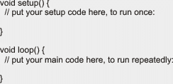
Here we discus and try to understand the fundamental minimum code that one would need to compile an “Arduino Sketch” which consists the setup()method and the loop()method.

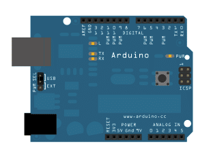
The only required Hardware for this is an Arduino Board, no additional circuit board is required.

warning message: electricity is dangerous, proceed with caution
Arduino bb 1

The setup() function is rendered as soon as a “sketch” is initiated. We enforce it in order to set forth the variables, pin modes, begin involving libraries, etc.

The setup operation is assigned for executing just once, every time the Arduino board is switched ON or is reset.

Once you develop a setup() functionality, the loop()function executes exactly what its named after, that is it begins looping successively, providing a chance to your program to alter and respond as it runs and moves ahead.

Code which comes under the loop() section of your “sketch” is enforced to vibrantly take control of the Arduino board.

The compiler will not read all those lines which might begin with a couple of slashes (//), which indicates that you are supposed to write your code only after this.

Expressing your code in this form ensures ease of explaining the folks who may be reading it, as well to yourself regarding how the program could be proceeding in a step by step manner.


arduino sketch 1


Blinking an LED with Arduino

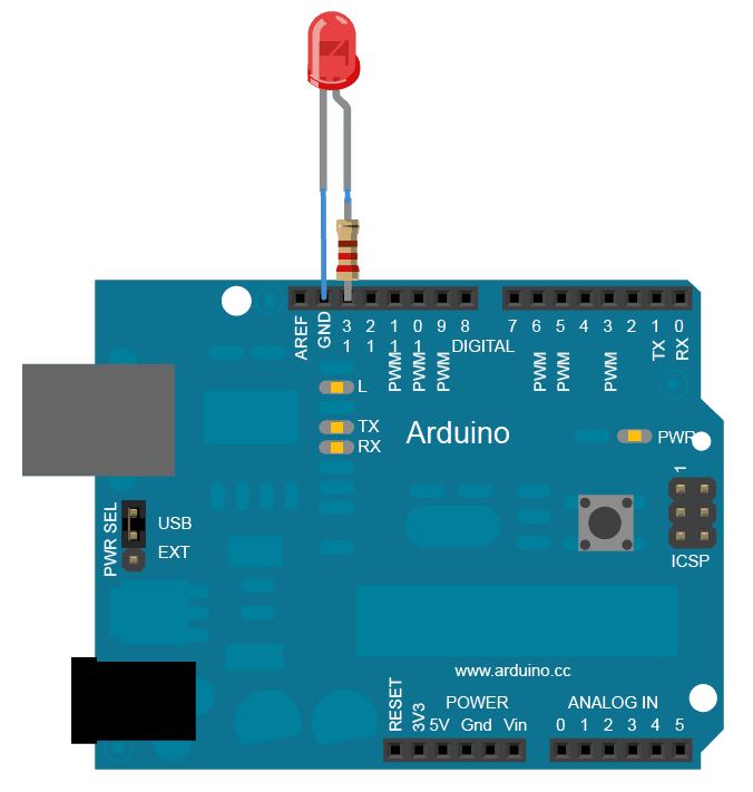
Here I have explained regarding the most basic electronic circuit operation that one can execute using an Arduino board, yes it’s about blinking an LED through a code.

The only additional device other than an Arduino board that you would require is an - LED.

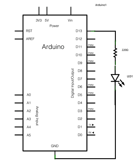
To begin with the procedure, you need to connect a 330 ohm ¼ watt resistor to pin#13 of the board.

Next, connect the LED with this 330 ohms resistor and ground (long lead goes to 330 ohm while the shorter lead to ground).Now hook up the Arduino board with your computer, initialize the program and feed the code tha’s presented later on this page.

Traditionally Arduinos would have an LED connected across its pin#13, which starts blinking when powered without any hardware involved.


Implementing the Code

In order to implement the code, the first execution would be to toggle pin#13 to form an output pinout with the line:

pinMode(13, OUTPUT);
Across the main loop, we switch ON the LED through the line:

digitalWrite(13, HIGH);

The above enables a 5V supply to pin#13 so that I generates the required potential across the LED, illuminating it.

Now we switch it OFF using the following line:

digitalWrite(13, LOW);

Yeah, logically this reverts pin#13 to zero, switching OFF the LED.

Now in between the above ON and OFF of the LEDs we would require a certain time delay gap, so that the blinking makes sense and becomes recognizable.

The code delay() commands Arduino to remain stationery until a second, in other words this command mutes
the operations for a second.
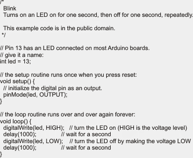
The Code:

arduino blink an LED with delay 1

You'll also like:

  • 1.  Wireless Thermometer Using 433 MHz RF Link Using Arduino
  • 2.  Converting Analogue to Digital (Analogue Read Serial) – Arduino Basics
  • 3.  Playing a Melody Using the Tone() function in Arduino
  • 4.  Monitoring State of a Switch (Digital Read Serial) – Arduino Basics
  • 5.  Types of Arduino Boards with Specifications
  • 6.  SMS Based Water Supply Alert System

Filed Under: Arduino Projects Tagged With: Arduino, Basics, Blinking, Delay, LED

About Swagatam

I am an electronics engineer and doing practical hands-on work from more than 15 years now. Building real circuits, testing them and also making PCB layouts by myself. I really love doing all these things like inventing something new, designing electronics and also helping other people like hobby guys who want to make their own cool circuits at home.

And that is the main reason why I started this website homemade-circuits.com, to share different types of circuit ideas..

If you are having any kind of doubt or question related to circuits then just write down your question in the comment box below, I am like always checking, so I guarantee I will reply you for sure!

Previous Post: « Electronic Scoreboard Circuit Using IC 4033 Counter
Next Post: Customized Water Flow Controller with Timer Circuit »

Reader Interactions

Comments

  1. Mitchell Perumal says

    July 24, 2015 at 11:52 am

    Hi SWA. I'm considering buying an arduino. It a Mega 2560 r3 with a starter kit. could you advise if its a reasonable choice to begin with. also can u use multiple inputs to activate their own sub-procedures at the same time Or assign varying interrupt level for certain inputs. Thank U.

    Reply
    • Swagatam says

      July 25, 2015 at 2:21 am

      Hi Mitchell, I am not so well versed with Arduinos, so won't be able to suggest correctly.

      Reply
    • VIJAY AJ says

      May 23, 2016 at 3:19 am

      Hi perumal, I suggest arduino uno is the best and cheapest one when you are at starting stage. First of all you try with arduino uno when you studied all the process such as spi,i2c,LCD,xbee e.t.c interfacing using arduino uno then you move for arduino mega….I got a clone version of arduino uno from Amazon at 450rs….it works well

      Reply
  2. shadab karnachi says

    December 1, 2014 at 1:37 pm

    I have atmega32,
    can we control 4 motors using atmega 32?

    Reply

Need Help? Please Leave a Comment! We value your input—Kindly keep it relevant to the above topic! Cancel reply

Your email address will not be published. Required fields are marked *

Primary Sidebar


Subscribe to New Posts

Categories

  • Arduino Projects (89)
  • Audio and Amplifier Projects (132)
  • Automation Projects (17)
  • Automobile Electronics (101)
  • Battery Charger Circuits (83)
  • Datasheets and Components (104)
  • Electronics Theory (143)
  • Free Energy (37)
  • Games and Sports Projects (11)
  • Grid and 3-Phase (19)
  • Health related Projects (25)
  • Home Electrical Circuits (12)
  • Indicator Circuits (14)
  • Inverter Circuits (88)
  • Lamps and Lights (142)
  • Meters and Testers (69)
  • Mini Projects (46)
  • Motor Controller (64)
  • Oscillator Circuits (27)
  • Pets and Pests (15)
  • Power Supply Circuits (108)
  • Remote Control Circuits (50)
  • Security and Alarm (64)
  • Sensors and Detectors (101)
  • Solar Controller Circuits (59)
  • Temperature Controllers (42)
  • Timer and Delay Relay (49)
  • Transmitter Circuits (29)
  • Voltage Control and Protection (39)
  • Water Controller (36)


Other Links

  • Privacy Policy
  • Cookie Policy
  • Disclaimer
  • Copyright
  • Videos
  • Sitemap


People also Search

555 Circuits | 741 Circuits | LM324 Circuits | LM338 Circuits | 4017 Circuits | Ultrasonic Projects | SMPS Projects | Christmas Projects | MOSFETs | Radio Circuits | Laser Circuits | PIR Projects |

Social Profiles

  • Twitter
  • YouTube
  • Instagram
  • Pinterest
  • My Facebook-Page
  • Quora
  • Stack Exchange
  • Linkedin


  • Recent Comments

    • Swagatam on 100A AC Load Monitoring Circuit using Arduino, Watt Limit, LCD, Alarm, Auto Shutdown
    • Swagatam on How to Modify 78XX, LM323, LM350, LM317 Voltage Regulator Circuits
    • Swagatam on 5 Simple Audio Mixer Circuits Explained
    • MOSES on 100A AC Load Monitoring Circuit using Arduino, Watt Limit, LCD, Alarm, Auto Shutdown
    • Hamid on How to Modify 78XX, LM323, LM350, LM317 Voltage Regulator Circuits

    © 2025 · Swagatam Innovations