• Skip to main content
  • Skip to primary sidebar

Homemade Circuit Projects

Need circuit help? Post them in the comments! I've answered over 50,000!

Blog | Categories | About | Contact | Calculators-online
You are here: Home / Arduino Projects / Arduino RGB Flowing Sequential Light Circuit

Arduino RGB Flowing Sequential Light Circuit

Last Updated on December 5, 2024 by Swagatam Leave a Comment

This Arduino RGB sequential light generator circuit will generate a smooth flowing red, green blue pattern over the connected RGB LED.

Table of Contents
  • The hardware required for this project:
  • Code:

The LED used here is a four pin 30mA RGB LED, common anode type, meaning the common pin for this LED will need to be assigned a continuous positive for the required operations. The LEDs that are specified as common cathode require a continuous negative or ground for the RGB illuminations.

The hardware required for this project:

One Arduino UNO board.
One 220 ohm, 1/4 watt resistor
One RGB, 5mm, 30 mA LED (common anode type)
Link Wires
Soldering iron,
9V adapter AC/DC

warning message: electricity is dangerous, proceed with caution

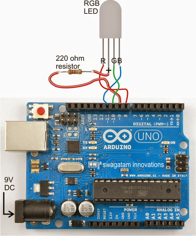
The connection details of the proposed RGB LED sequential light circuit using Arduino can be seen in the above diagram.

The connections are pretty easy to implement, just insert the LED leads to the Arduino burg pinouts, switch the the power socket and visualize the RGB LED running the red, green, blue illuminating in a sequential manner.

The code is fully customizable as per the individual preferences and selections,

Code:

Then sketch code for this RGB LED sequential flowing light circuit can be found as given below:

/*
RGB LED color flow
Displays a [fairly] smooth
sequence of colors on an RGB LED

by Jeremy Fonte
Copyright (c) 2012 Jeremy
Fonte.  All rights reserved.
This code is released under the
MIT license:

https://opensource.org/licenses/MIT*/

int r = 0;
int g = 0;
int b = 0;

int ri = 1;
int gi = 3;
int bi = 2;

// the setup routine runs once when you press reset:
void setup() {
// initialize the digital pin as
an output.
pinMode(8, OUTPUT);
pinMode(9, OUTPUT);
pinMode(10, OUTPUT);
pinMode(11, OUTPUT);

digitalWrite(9, HIGH);
}

// the loop routine runs over and over again forever:
void loop() {
r = r + ri;
g = g + gi;
b = b + bi;

if(r > 255) {
r = 255;
ri = -1 * random(1, 3);
}
else if(r < 0) {
r = 0;
ri = random(1, 3);
}

if(g > 255) {
g = 255;
gi = -1 * random(1, 3);
}
else if(g < 0) {
g = 0;
gi = random(1, 3);
}

if(b > 255) {
b = 255;
bi = -1 * random(1, 3);
}
else if(b < 0) {
b = 0;
bi = random(1, 3);
}

analogWrite(8, r);
analogWrite(10, g);
analogWrite(11, b);
delay(20);
}

You'll also like:

  • 1.  Battery Over Charge Protected Emergency Lamp Circuit
  • 2.  Automatic LED Candle Light Circuit
  • 3.  Neon Lamps – Working and Application Circuits
  • 4.  Fading an LED ON/OFF – Arduino Basics
  • 5.  Arduino Pure Sine Wave Inverter Circuit with Full Program Code
  • 6.  H-Bridge Sine Wave Inverter Circuit using Arduino

Filed Under: Arduino Projects, Lamps and Lights Tagged With: Arduino, Flowing, Light, RGB, Sequential

About Swagatam

I am an electronics engineer and doing practical hands-on work from more than 15 years now. Building real circuits, testing them and also making PCB layouts by myself. I really love doing all these things like inventing something new, designing electronics and also helping other people like hobby guys who want to make their own cool circuits at home.

And that is the main reason why I started this website homemade-circuits.com, to share different types of circuit ideas..

If you are having any kind of doubt or question related to circuits then just write down your question in the comment box below, I am like always checking, so I guarantee I will reply you for sure!

Previous Post: « Arduino Musical Tune Generator Circuit
Next Post: Arduino LCD KeyPad Shield (SKU: DFR0009) Datasheet »

Reader Interactions

Need Help? Please Leave a Comment! We value your input—Kindly keep it relevant to the above topic! Cancel reply

Your email address will not be published. Required fields are marked *

Primary Sidebar

circuit simulator image

Subscribe to get New Circuits in your Email


Categories

  • Arduino Projects (89)
  • Audio and Amplifier Projects (132)
  • Automation Projects (17)
  • Automobile Electronics (101)
  • Battery Charger Circuits (83)
  • Datasheets and Components (105)
  • Electronics Theory (143)
  • Free Energy (37)
  • Games and Sports Projects (11)
  • Grid and 3-Phase (19)
  • Health related Projects (25)
  • Home Electrical Circuits (12)
  • Indicator Circuits (14)
  • Inverter Circuits (88)
  • Lamps and Lights (142)
  • Meters and Testers (69)
  • Mini Projects (46)
  • Motor Controller (64)
  • Oscillator Circuits (28)
  • Pets and Pests (15)
  • Power Supply Circuits (108)
  • Remote Control Circuits (50)
  • Security and Alarm (64)
  • Sensors and Detectors (102)
  • Solar Controller Circuits (59)
  • Temperature Controllers (42)
  • Timer and Delay Relay (49)
  • Transmitter Circuits (29)
  • Voltage Control and Protection (40)
  • Water Controller (36)


Other Links

  • Privacy Policy
  • Cookie Policy
  • Disclaimer
  • Copyright
  • Videos
  • Sitemap

People also Search

555 Circuits | 741 Circuits | LM324 Circuits | LM338 Circuits | 4017 Circuits | Ultrasonic Projects | SMPS Projects | Christmas Projects | MOSFETs | Radio Circuits | Laser Circuits | PIR Projects |


Social Profiles

  • Twitter
  • YouTube
  • Instagram
  • Pinterest
  • My Facebook-Page
  • Quora
  • Stack Exchange
  • Linkedin


  • Recent Comments

    • Swagatam on Crystal Radio Sets with Amplifier Circuit
    • Lion on Crystal Radio Sets with Amplifier Circuit
    • Swagatam on How to Make Dog Barking Preventer Circuit using High Frequency Deterrence
    • Swagatam on 5 Simple Fastest Finger First Circuits Explained
    • suat kaleli on How to Make Dog Barking Preventer Circuit using High Frequency Deterrence

    © 2025 · Swagatam Innovations