An AC bridge is a circuit which can be used for measuring parameters like capacitance, resistance, Inductance using differential method, by comparing them with known values of similar components, positioned diagonally across a bridge circuit, and through an analogue meter placed at the center of the bridge.
Before we begin talking about the AC bridge circuits using capacitance and/or inductance, it may be important to understand several related terminologies. The capacitors and inductors that are ideally suited for the application are specified with reactance in an AC circuit, instead of resistance.
Important Parameters
Reactance represents the AC variant of "resistance," which is indicated in ohms. Impedance is one more relative term which is utilized to express the whole combined result of reactance and resistance in certain section of a circuit, and is indicated in ohms.
In the practical world capacitors and inductors both may consists of resistance and reactance, therefore while talking about them we imagine them also having an impedance and not just only reactance.
Since the AC bridge circuit legs might consist of both reactances and/or resistances, we'll discuss these legs of the bridge with regard to impedance and not resistance.
To be precise , resistance and impedance can be incredibly identical. The factors for keeping an AC bridge balanced are exactly the same as a DC bridge, we only insert an impedance (symbolized as Z) instead of the resistance.
This provides us with extremely standard equations which can be used with any relevant circuit.
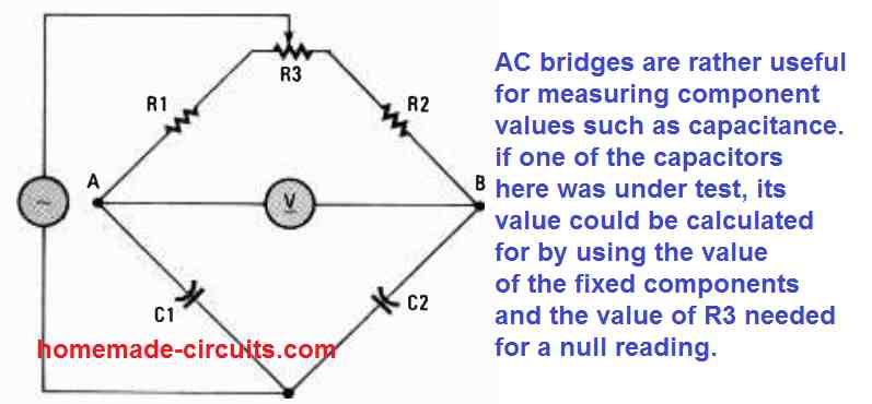
AC bridges work quite well for calculating component values, for example the capacitance. In case we had a capacitor here under test in an AC bridge circuit, its value could be determined utilizing the values of the components in the bridge whose values are known, along with the value of R3 which may be necessary for implementing the null reading.
1) Measuring Small Capacitance Differences
In case we want to determine small differences in capacitance of a capacitor, we could start using an AC bridge circuit like the one shown in Fig. 1 below. Considering that a resistor's impedance is strictly resistive and a capacitor's impedance is practically completely reactive, the impedance of the upper branches of the bridge simply cannot can be different to the lower branches.
In this circuit R1/C1 = R2/C2 when the R3 is correctly adjusted for getting a zero or null reading on the voltmeter V.

This indicates that the second set of conditions needed for balancing (ZA = Z3 and Z4 = ZB) cannot be be fulfilled. The third conditions required for balance the AC circuit cannot be fulfilled either.
Having said that, we can see that the initial conditions (ZA = ZB and Z3 = Z4) could be fulfilled. The impedance ZA consists of R1 and a part of R3, while the impedance ZB comprises of R2 and a some part of R3. The impedance Z3 is attributed to the capacitor C1, while Z4 is the impedance that is used to represent C2.
Provided that C1 remains equal to C2 and any R1 and R2 difference is tweaked and corrected by R3, then we can achieve a well balanced bridge.
Here the impedance of active components, such as resistors and capacitors is determined by the frequency. However we find that the Fig. 1 is not dependent on frequency because the C1, C2 reactances could alter together whenever the frequency changes.
An additional variant of the above discussed AC bridge circuit can be seen in Fig. 2. Although this circuit is designed to work well, it isn't one of the favorite AC bridge versions due to the presence of the DC isolation across only one side of the meter (at point B).
In this circuit R1/R2 = C1/C2 when the variable resistor R3 is appropriately adjusted to get a zero or null reading on the meter V.
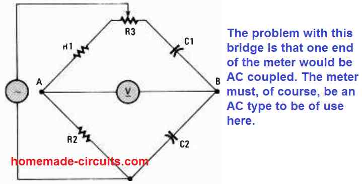
If a DC content comes through the input source, it could result in much unfavorable effects. Additionally it could be complicated to bias a meter-input amplifier hooked up at point A without modifying the input signal level at A.
2) Using Only Capacitors
It is possible to create an AC bridge circuit using only capacitors as demonstrated in Fig. 3 below.
In this circuit, C1/C2 = C2/C4, when the variable resistor R1 is carefully adjusted until a zero or null reading is obtained on the meter V
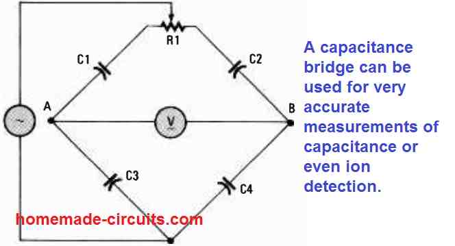
Let's analyze the initial condition (ZA = ZB and Z3 = Z4). Given that the reactance of the capacitor pairs C1/C2 and C3/C4 can change in the same way in response to the changing frequency, the balanced state of the AC bridge is not dependent on the frequency.
Need Help? Please Leave a Comment! We value your input—Kindly keep it relevant to the above topic!