This E-bike or electric bike circuit I have explained below can be used as the control circuit for constructing a homemade E-bike, with the help of a permanent magnet motor DC (PMDC motor), and a Li-Ion battery.
An electric bike is basically a bicycle powered through a motor and a battery, which does not require a manual pedaling for operating the bicycle. In some bikes a manual pedal assistance is also provided.
In this post we won't be discussing the entire wheel mechanism of the E-bike, rather we will only learn how to build the control circuit for the motor, and a finger press accelerator mechanism.
The whole idea is designed by me, with perfect understanding and brain simulation. However, the final design will need to be tested practically to confirm the proper working of the E bike circuit.
The idea is actually quite unconventional since this E-bike is supposed to operate without any pedal assistance. Instead the bike will depend entirely on the battery power. The battery could be charged externally through a suitable battery charger unit and grid power.
Basic Working
The E-bike project basically includes two elements, A PWM motor controller circuit and a finger press operated throttle or accelerator circuit. More information regarding the basic working details of the system is given below:
- A PWM motor controller circuit which responds to an external signal and proportionately varies the speed of the motor through a correspondingly varying PWM output.
- A finger press accelerator unit, consists of an LED and an LDR, arranged one beside the other. The light from the LED is directed on a shaft and is reflected back towards the LED. The amount of light reflected from the shaft is determined by the proximity of the shaft towards the LED/LDR module, which is in turn determined by how much the shaft is depressed towards the LED/LDR arrangement.
- The pressing of the shaft is implemented by pushing a attached push button, by the rider.
- As the button is pressed deeper, the attached shaft moves closer to the LED/LDR module causing an increased amount of light to get reflected on the LED.
- As the light on the LDR increases, the LDR resistance decreases, and this information is converted into a signal which causes the PWM width from the PWM controller to increase.
- The increase in the PWM width causes the E-bike motor speed and torque to increase, which in turn causes the speed of the E-bike accelerate.
- When the pressing of the accelerator button is slowly released, the opposite response is achieved, which causes the PWM width to decrease and a subsequent reduction in the acceleration of the E-bike speed.
Finger Press Accelerator (Throttle)
The function of the finger press accelerator is to provide the rider a facility through which he or she can increase or decrease the speed of the E-Bike motor through a corresponding pushing or releasing of the accelerator push button.
As explained above, the working of the finger pressed accelerator unit can be understood through the following points, and by referring to the following two diagrams.
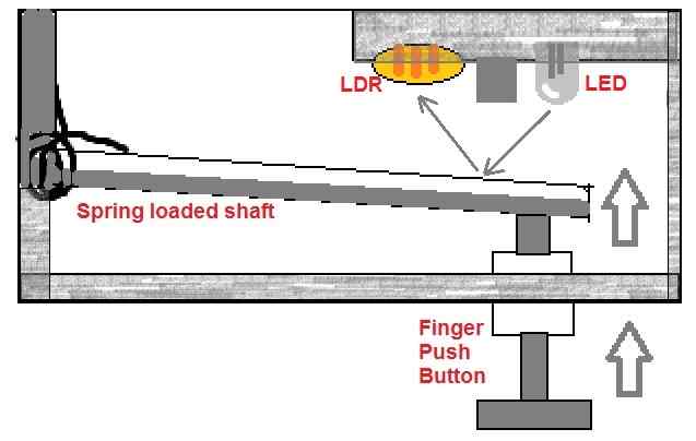
As can be seen the above diagrams, the finger push accelerator for the E-Bike consists of a spring loaded shaft, which is mechanically attached to a push button.
We can also see an LED/LDR arrangement fixed parallel to the spring loaded shaft, such that the light from LED can fall on the inner surface of the shaft and get reflected towards the LED. The amount of light that can be reflected depends upon the proximity of the shaft toward the LED/LDR configuration.
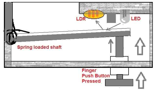
Due to the spring tension, the shaft pushes the button outwards. When the push button is pressed with finger, it pushes the shaft inwards causing it move closer towards the LED/LDR module.
As the shaft is pushed harder, the shaft moves closer to the LED/LDR assembly causing proportionately greater amount of light to be reflected from the LED to the LDR.
This causes the LDR resistance to decrease. Now, if the pressure on the push button is loosened, the shaft moves away from the LED/LDR assembly causing a proportionately lower amount of light to be reflected towards the LDR. The LDR resistance now increases.
The above increase and decrease in the LDR resistance value is sent to a PWM controller circuit.
Here, the varying LDR resistance is appropriately converted to a signal which causes the PWM circuit to generate a correspondingly varying PWM signal output.
PWM Controller Circuit
The function of the PWM controller circuit is to sense the varying resistance of the LDR and convert it into a correspondingly changing PWM output. The PWM output is then fed to the E-bike motor for achieving the required speed control.
The circuit is built around a couple of IC 555, as shown in the following figure.
The working of the motor PWM controller circuit can be understood with the following points.
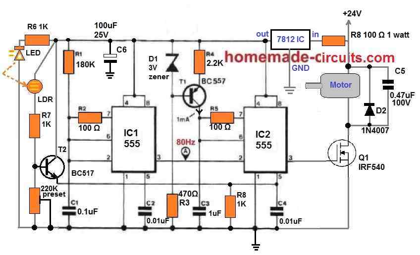
IC1 is configured as a simple 555 astable multivibrator circuit which generates a 80 Hz rectangle wave output at its pin#3.
This 80 Hz frequency is sent to pin#2 of IC2 which is another IC 555 configured as a PWM generator.
The 80 Hz frequency is first converted to 80 Hz triangle wave with the help of an RC integrator built around R4/C3 via T1.
This triangle wave is fed to pin#6 and pin#7 of IC2, which is subsequently compared with the voltage at pin#5 of IC2 to generate the corresponding PWMs at pin#3.
Thus, depending upon the potential level at pin#5, the output pulse at pin#3 of IC2 can vary from thinner to wider PWMs and vice versa.
The potential at pin#5 of IC2 is determined by the emitter voltage of T2.
T2 being configured like an emitter follower, produces an emitter voltage which is perfectly equivalent and in sync with its base voltage.
The base voltage of T2 is determined by the resistance of the LDR, which is in turn determined by the reflected illumination from the adjacent LED lamp.
How the light from the LED is reflected on the LDR is already explained earlier, under the "finger press accelerator" paragraphs.
Therefore, as explained before, when the shaft inside the finger press accelerator unit is pushed closer to the LED/LDR assembly, the light on the LDR decreases, causing higher amount of potential difference to be generated at the base of T2.
T2 being configured as an emitter follower, causes this rising potential to be sent to the pin#5 of the IC2.
IC2 now translates the same into an increasing PWM at its pin#3.
Exactly the opposite happens, that is reduction in the PWM happens when the accelerator shaft is slowly released, due to a decreasing illumination on the LDR.
How to Implement the E-Bike Circuit
Implementing the proposed electric bike circuit is just about hooking up the PWM controlled motor with the rear wheels of a bicycle.
The bicycle may have a pedal assist, however unlike conventional E-bikes, here the pedaling is not used for initiating the PWM circuit.
The PWM motor controller can be initiated simply by pressing the accelerator button.
However, if the bicycle is not first initiated through manual pedaling could cause a lot of strain on the motor and the battery, and the motor may be unable to push the bike forward.
Therefore, it is necessary to generate some initial kinetic energy on the bike through pedaling and only then push the accelerator switch, so that the motor can further assist the rider, allowing the pedaling to get easier.
Motor Specifications
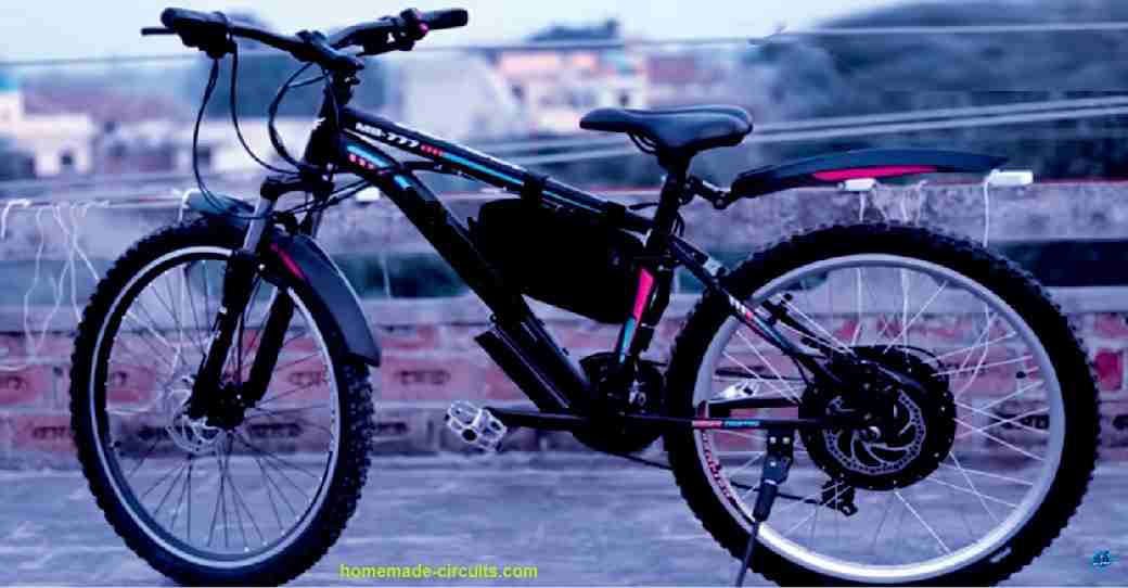
The suggested motor for the above E-bike project is a 24V 250 watt permanent magnet DC motor (PMDC), as shown below:
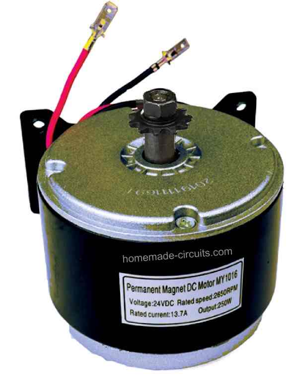
An attached gear box is not required for the proposed application, since the circuit is PWM based, and the initialization of the motor will be soft and slow, rather than quick and abrupt.
Using Force Resistor for Throttle Controller
For the finger press accelerator unit, if you find the LED/LDR assembly mechanics a little cumbersome, you can easily replace it with a force sensing resistor for getting the same results with higher efficiency, and in a more compact way. The modified design can be witnessed in the following diagram.
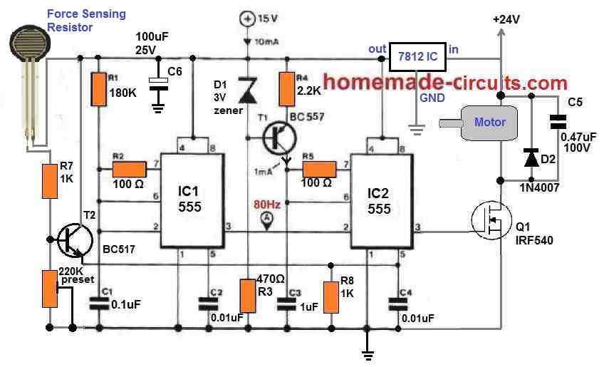
When pressure is applied on the force sensing resistor through finger pressing, the resistance of the force sensing resistor drops quite linearly, which is translated into PWMs with increasing width. The motor thus gains speed and acceleration.
When the finger is released, the pressure is withdrawn from the force sensing resistor, causing the PWMs to get narrower. The speed and acceleration of the E-bike motor now deceases proportionately.
Since the force sensing resistor can be quite sensitive to pressure changes, it is recommended to use a thick rubber pad over the resistor, to blunt of the response a bit.
Battery Specifications
The battery recommended for the above E-bike circuit is a 24V 10 Ah Li-ion Battery. A 15 Ah rated battery can be even better than a 10 Ah battery. The example of the battery can be seen in the following image.
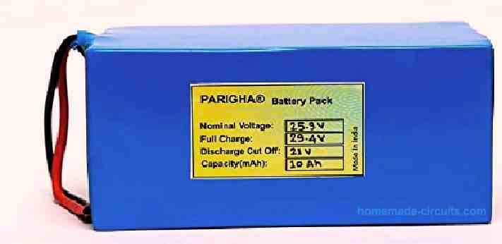
The voltage of the battery will need to be monitored through a low battery indicator circuit, or through a digital voltmeter or both.
Once the battery voltage reaches below 22 , it must be removed from the E-bike and charged at home through an appropriately rated Li-Ion charger.
This concludes the construction details of our simple E-bike controller circuit.
If you have any specific questions related to the subject, please fee free to post them through comments below, I'll most happy to answer them.


Questions & Answers
Can I use a lead acid battery for this project and a potentiometer also
Hola buenas tardes pregunta usted podría hacerme un favor de
Explicarme que estoy haciendo mal porque no funciona ya y se pruebas con el control batería, y todo lo demás, no sé qué pasa, pero estoy un poco frustrado
Hey, how did you test the circuit? Remember you must test the prototype first on a work bench and confirm the working of the stages using oscilloscope, and then fine tune the results, and then finally use it in the actual bike application..
No, lead acid battery will not work for an E-bike.
you have the best site on the
internet, well organized and clear
understanding. best of health
I am using a motor picked form a DC water pump rated 12v -36v, the pump could solar panels if up to 160watts so i hope to use at at 24v with 2 x 12ah batteries in series. Will this controller work well with it
Please build a smaller model first and check with a small motor, if everything works correctly then you can try the bigger motor as specified by you.
Hi!
i am really interested about this project , but can it handle 500w dc washing machine motor on this regulator? do i need some extra changes in scheamtic to handle it , ?
Sure, you can use use a 500 watt motor with this circuit, just make sure to replace the IRF540 mosfet with two nos of IRF3205 mosfets in parallel.
Nice thank you for response, i really apriciate it but i have still some questions, can 7812ic stay a high current wich is provided to motor or its better to power all pwm regulation from different supply and only mosfets will be on 24v?
thanks for response
You can supply any amount of current to the 7812 IC input as long as the voltage is below 35V. So for your 24V supply you can use the same motor supply for the 7812 IC also, no problems at all.
Thats looks nice, do you test this controller in real conditions ? what are the pros and cons ? it is relaiable ?
thanks for response
The IC1 and IC2 PWM motor control is fully tested…but I did not test it on a real bike.
nice, i think i would try this project if i have some problems with it can write on this forum ?
Sure, if there’s any problem you can ask here.
You might include a note that this circuit will NOT drive any of the wheel hubmotors that are so common in ebikes today; those are all three-phase nine-pole, and this circuit will just make a ruin of things with them. They require no less than nine H-bridges.
The motor specifications has been clearly mentioned in the article. This is a simple, cheap, DIY project, not a professional E bike circuit.
I see you had second thoughts about that statement. 8) Good. I approve.
Funny. I didn’t spot them, and if I didn’t, you can bet that about 80% of the people who read it also won’t have spotted them… especially those looking for a quick fix in copying someone else’s schematic. Those are the guys who accidentally wind up with a lithium fire on their bike, which is in the living room, resulting in an apartment building burning down.
Dang.
I’m going to assemble this project later I comment here, thank you very much partner.
sure, all the best to you.
I bought a e-bike 18 mths back although it is good, but Thank you so much for this circuit, Many want to go in for an e-bike and I can give this for them to follow, My Grandson also wants, so I will ask to build one with this, can you tell me the speed and how many hours it will go on one charge please. I will be grateful, I am 78 years old but still ride,
Thank you so much Mr Swagatam and looking for more of your innovations, Late in my life but still I dabble in this
May the almighty Bless you.
Thank you so much Colin, I am glad you liked this project. I am sorry, presently I am not sure about the speed and how many hours the battery may last….these will need to be tested practically. I hope your Grandson is able to build this circuit successfully. Let me know if you have any issues with the project, I will try to help.
I wish you all the best, and May God bless you too!
Beautiful and very useful circuit. Thank you for posting this.
Thank you, glad you liked it!