In this post I have explained how to make an interesting yet simple running LED cross sign or plus sign module for displaying in front of medical stores.
Nowadays, it is very common to witness illuminated flashing, chasing LED cross signs in front of medical stores, which work like an advertisement board for attracting the attention of the people around.
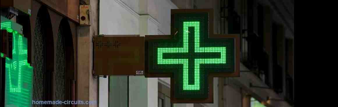
The cross sign is made up of high power, high bright colorful LEDs, mostly green, blue, yellow or violet.
The entire array of LEDs is controlled by a programmable LED driver controller which illuminates various group of LEDs in varied sequences, causing the LEDs to run and illuminate in many different attractive sequences.
In this article, we are going to build a rather simple circuit based on the popular IC 4017 and IC 555 chaser circuit, and try to create an attractive LED plus sign pattern.
The sequencing pattern will be in the manner as shown below:

Here we can see how a green plus sign or cross sign seems to grow from small to big in 4 steps, and then 4 arrow signs seem to run on a specific direction to indicate the location of the medical store.
Since in the actual prototype the arrow signs cannot be placed on top of the green LEDs, the final assembly could look something like this:
Circuit Diagram and Description
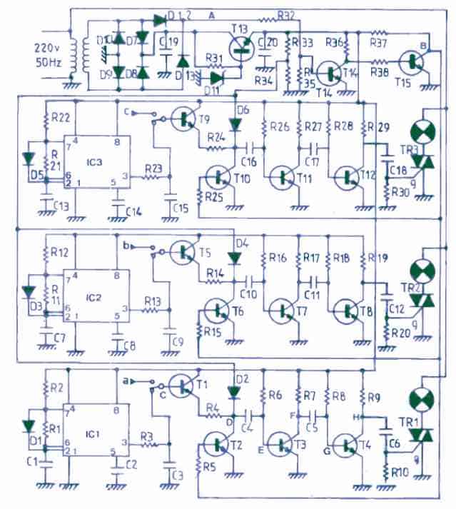
The circuit for the proposed LED cross sign lamp for medical stores can be accomplished using a simple 4017 and 555 IC based chaser circuit as depicted in the following diagram.
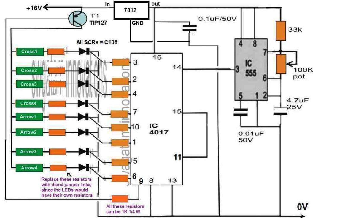
The working of the LED cross sign can be understood wit the following points.
When power is switched ON, the IC 555 begin sending clock pulses to pin14 of the IC 4017.
This causes the outputs of the IC 4017 to become high sequentially from pin3, 2, 4....and pin9, pin11.
However, while the sequence proceeds, each of the output becomes high and shuts off, so that the next pinouts subsequently become high and shut off, and so on.
This means only one pinout in the sequence remains high at any instant, while the others shut off.
But we don't want this to happen, otherwise the cross sign won't illuminate the way it is supposed to be.
We need something that would latch the outputs of the IC 4017 while sequencing so that each of its output remain high continuously until the sequence has reached the last pinout, which is pin9 and pin11.
Using SCRs for Latching LED Illumination
To implement the latching function, we have used SCRs across all the outputs. This ensures that as soon the relevant pinouts become high, the SCRs latch one by one, causing the relevant LED group to latch and glow continuously.
So, when power is switched ON, the 4017 output begins shifting from pin3, which causes the pin3 LED cross1 segment to glow and latch. Then pin2 becomes high, causing the relevant cross2 to illuminate and latch.
This sequential illumination and latching of the various LED cross signs and arrow signs is completed when the 4017 sequence reaches pin6 after which the sequence switches at pin9.
So far the pin9 had been low, which allowed the transistor TIP127 to remain conducting and allow the supply to the all the relevant LED groups via the relevant SCRs.
However, as soon as the sequence reaches pin9, it becomes high, causing the base of the transistor to cut off, which switches the transistor OFF.
When this happens, all the SCRs latching are disrupted and broken.
Due to this all the LED groups shut off simultaneously.
In the next step, the sequence hits pin11, which is connected to pin15, the reset pin of the IC.
This last sequencing operation causes the IC to reset, allowing the logic sequence to go back to pin3, so that the cycle can now repeat once again. The process keeps repeating in this manner accomplishing the intended LED cross sign pattern.
How the LEDs are Connected to the SCRs
The entire cross sign is divided into various LED series/parallel groups, and each of these groups are connected with the 8 SCRs in the circuit.
All the positives of the cross sign and the arrow sign LED arrays are connected with the collector of the transistor TIP127, while all the negatives are connected with the anodes of the SCRs.
Now I have explained how the various LED groups are arranged in the cross sign and the arrow signs, through series and parallel connections.
Cross1
The cross1 LED group forms the central part of the cross sign, through which the sequencing is initiated. The following figure shows how the LEDs are connected in this group.
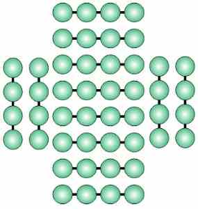
Here we can see that there are in all 12 LED strings having 4 LED on each string. It is required to connect a 100 ohm resistor in series with each of the strings, anywhere between resistors. For example you can insert the series resistor after two LEDs on each of the strings.
Once all the strings are arranged in the indicated fashion, the positives of all the strings must be connected together, and all the negatives connected together. This will give you one common positive wire and one common negative wire. These two wires will now need to be connected across the anode of the first SCR.
Cross2
For the cross2, we will add one LED string across the top, bottom, left, right arms of the cross1, as indicated in the following image.
In cross2 we have 4 strings of LEDs each having 4 LEDs and one 100 ohm series resistor. Just as above you will have connect all the common positives and common negatives together to get a pair of positive and negative wires. These wires will connect across the anode of the second SCR.
Cross3
Just as cross2, we add one more segment of LEDs across the ends of the two arms of the cross, as depicted in the next figure below:
We can see how the cross is slowly getting bigger, as the LED strings are being repeated across the edges of the two arms of the cross.
Here too the LED strings have 4 LEDs on each string, with one series 100 ohm resistor between two LEDs on each strings.
Join the positives in common, and negatives in common and connect these wires across the anode of the 3rd SCR.
Cross4
Cross4 is yet again a repetition of a single segment of LEDs strings across the ends of the cross arm, which finally completes the full dimension of the cross, as shown in the following figure.
Here also we find there are 4 LED strings. A 100 ohm series resistor is held between two LEDs on each of the strings. Just as before, join the positives in common, and join the negatives of the strings in common, and connect the wires across anode of the 4rth SCR.
This completes the construction of the cross sign LED array. While sequencing through the SCRs, cross1 LEDs illuminate first, then cross2 LEDs illuminate, then cross3 LEDs light up, and finally the cross4 LED strings illuminate giving an impression that the cross is slowly getting bigger.
Arrow sign
The arrow sign has 8 groups of LEDs arranged in the form of arrows, as shown in the above figure.
Each arrow sign consists of 5 series LEDs, with a 50 ohm series resistor, which can be connected anywhere in series with each LED string.
LED series A and A are connected in parallel, meaning their positives and negatives are joined together, and these common +/- wires are attached across the anode of the 5th SCR.
Similarly, the B and B LEDs are connected in parallel and hooked up across the 6th SCR.
Likewise, the LED strings C and C are joined in parallel, and strings D and D are connected in parallel, and these LED groups are connected across the 7th and the 8th SCRs respectively.
The concludes the construction of the entire LED cross sign.
Now let;s learn about the power supply details.
Power Supply
The power supply should be built using a 0-12V/2 amp transformer, with appropriate bridge rectifier and filter capacitor circuit network, as shown in the following image.
The output voltage of the power supply can be calculated using the following formula:
Peak DC = RMS voltage x 1.41
= 12 x 1.41 = 16.92V
This 16V Dc is fed to the chaser circuit where the whole 16V DC is used for illuminating the cross signs and the arrow sign, while the same voltage is dropped to 12V DC using IC 7812, for the 4017 and 555 circuit stages.
Which LEDs to be Used
The best suitable LED that can be used for this medical store LED cross sign display is the green high bright straw hat LEDs or piranha LED. The following image shows the examples of straw hat LED in green and yellow color.
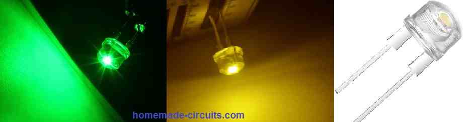
The straw hat LEDs are rated at 3.3V 50 mA, and are dazzling bright and seem to be perfectly suited for making the above explained LED cross sign or LED plus sign advertisement board for medical stores.
The above explained LED cross sign display can be modified in many innovative ways to create many different LED patterns. Here's one new example which can be also tried using the same driver circuit explained above.


Questions & Answers
Hello Sir.
I need LEDs to display on a 20cm by 25cm area for a SMART CUSTOMIZABLE NOTICE BOARD FOR ENGINEERING DEPARTMENT UPDATES that uses arrays of LEDs and a Bluetooth communication.
The updates should be displayed vertically in a list-like manner with the name of the department permanently on top, then the updates follows below it.
I intend to use Arduino, HC-06 Bluetooth Module and TLC5940 – PWM Driver with approximately 500 LEDs, (5mm) with a spacing of 1cm.
How do I go about it Sir? Are these right choice of the requirements? do you have a circuit guide for me please?
Hello Jedidiah,
That will require quite a complex circuitry and coding, and may not be possible for me because my Arduino programming is not good.
Your website is awesome full of knowledge. Thanks
Thank you very much!
This a wonderful job. Thanks a lot. Regrettably, what is available here is 5mm/20mA transparent LED that produces green when powered. I hope is okay enough and compatible with the circuit.
Thank you Moses, yes the LEDs must be powerful so that they are visible from long distances. 20 ma LEDs might not produce sufficient brightness.
Congratulations!
Very fascinating project.
Thanks for your feedback!
un grand merci pour toutes ces informations
You are welcome
ce sont des leds de 8mm ?
Can be 8mm or 5mm as per requirement and size of the cross.
Love your circuit for the cross very simple and easy to make very refreshing to see a circuit without a processor and using the 555 the 555 must be the most adaptable chip every made
Thanks, Bob
Thank you very much, glad you liked it!