In this article we study an RF discharge generation concept also called EMP generator capable of producing an intense RF electrical discharge in the air which may have the potentials of paralyzing and permanently damaging all electronic systems in the close vicinity. The idea was requested by Mr. Nidal.
Technical Specifications
I have seen a lot of circuits from you in your blog. I am a great fan of you!!!!
If you could help me with a circuit diagram for breaking 2.5 Volt torch bulb (Filament type) when it is switched ON and kept close to a copper pot 6 inches away (distance is between torch and copper pot) with a 12 Volt DC supply.
The thing is that, a switched on torch bulb should blow off when it is kept closer to a "copper pot" kept 6 inches apart. I hope a strong magnetic field will give the result.
But the problem is how to magnetize a copper pot to that extend?, an alternating supply give to a copper pot may develop magnetic flux around it or will it get short circuited?
Is it enough to break lamp filament? Or do I need to wind a copper coil inside that vessel to get that result?
Please help me in solving this issue.
Many thanks and expecting a reply from you soon.
Best regards,
Nidal.
The Design
The proposed concept of fusing a bulb filament through a wireless magnetic field doesn't appear to be feasible, however it could be implemented using a very strong RF discharge, such as from a very high voltage capacitor.
The idea may be carried as given in the following explanation:
A high current low voltage is first stepped up to many kilovolts, then stored inside equivalently rated high voltage capacitors and finally discharged by creating a short circuit across the high voltage capacitor leads.
The resulting discharge will generate an awesome amount RF electricity in the zone which may have the potential of fusing the filament of a bulb or illuminating a fluorescent tube momentarily.
Caution: The EMP discharge could produce devastating effects on all electronic equipment placed within the range of the discharge.
Caution: This circuit is designed to generate extremely high lethal voltages. Extreme caution and care is advised while handling this project. This project is NOT recommended for the newcomers.
Circuit Diagram
How it Works
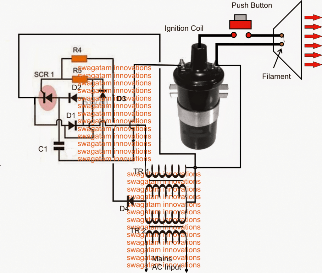
Referring to the diagram above, the set up shows a basic capacitive discharge system. The circuit comprising the diodes, C1 and the SCR form a capacitor charge/discharge switching stage which is powered from a boosted AC using a couple of mains transformers.
TR1/ and TR2 transformers are coupled together such that the low voltage TR2 winding connects with the TR1's low voltage winding.
When mains is applied to TR2 primary, an equivalent 220V (low current) is induced across the upper winding of TR1.
This voltage is used for charging the high voltage capacitor C1 in the circuit via a switching SCR stage which is triggered through the 50Hz low voltage input from TR2 via D2.
The switched C1 discharge is applied to the primary of a car ignition coil, which steps up this voltage to a staggering 40,000V or higher.
This voltage is kept hanging across a thin filament position within a suitably dimensioned conical shaped aluminum radiator.
When the shown push button is pressed, the high voltage tries to force its path through the filament creating a massive arc and explosion across the points.
This generates an intense RF disturbance in the region which is further magnified and propagated by the cone to the target which is here a small electrical bulb.
If the discharge is sufficiently strong may produce a momentary illumination of the bulb filament and then fusing due to the generated RF electricity.
Parts List
- R4,R5 = 100 OHMS, 1 WATT
- D1, D2, D3, D4 = 1N4007
- C1 = 100uF/500V,
- SCR = BT151
- TR1/TR2 = 220V/0-12V/1AMP TRANSFORMERS.


Questions & Answers
Mr Swagatam, did I understood it right? I mean 2 220/12V transformers wired back to back to make a 220V supply that is galvanically insulated from mains is used to charge a capacitor via SCRs to dump the capacitor charge, witch at this point I assume is around 360V? into an automotive ignition coil to give over 40KV of RF output and the switch is on the HV portion of the ignition coil? is my understanding correct? sorry because the drawing really got me confused there for a bit.
H William,
yes, your assumption is perfectly correct!
Those people asking for this circuit are using to cheat the society in India. The rate of the pot increases with the range of the torch closing. Starts from lakhs to crores………. Its a illegal business in India
Could you please give me a step-by-step on which terminal I’m soldering these different pieces to on the transistor I do not understand this diagram and I bought the pieces for this thing and I need it to work. Or can you just send me a picture of one that does work?
Where can I buy the Transformers for this and could you send me just a picture of what it looked like if you put it together just the circuit with? The Transformers and the capacitor.
You can buy the transformer from any car automobile shop.
It is basically a powerful CDI circuit. You can refer the following example article and the video:
https://www.homemade-circuits.com/how-to-make-capacitive-discharge/
I still don’t understand the wiring diagram which terminal of the transistor do I wire the full Bridge rectifier to?
I am sorry, but if you are not understanding the circuit then this experiment is not for you. This project involves lethal high voltage and and I won’t recommend this to any newcomer.
I’m not new to electricity I just have a hard time with these bolueprints.
Isn’t there two of the Transformers and are they the same values as one another? I’m new to electronics so I have no idea how to read these diagrams that’s why I asked for a picture. What should I charge the capacitor with?
Yes they both can be 0-12/220V 1 amp transformers with their 12V side wires connected with each other.
And what kind of tr is it ac to DC or DC to ac DC to DC or ac to ac?
Transformers always work with an input AC, and produce an equivalent AC output depending on the winding spec.
U have written it as 0-12v 1 amp and 220v0-12v I amp are these step up or down tra nsformers?
These are the standard step-down transformers.
I need to build a simple mobile RFI jam out of household things what can I use and how ?baby monitor ? Walkie talkie ?remotes??? Please help
It is not possible to build a mobile phone jammer using household gadgets. Jammers require special parts.
How much is the power of this circuit and can it be modified to have much more power? If yes then please provide the schematic.
The power will depend on the ignition coil power and the transformer power. I have not yet checked the actual power of the system so not sure about it.
Have you done this
Hi sir, please check your mail.i have been attached a video.
Hi Manu, I cannot find your email, not even in junk folder
This is your mail id right???
Got your email now, what you are showing is basically a Tesla Coil, as given in the image
Sir thank you soo much.
Sir I need this same method above the one table.i need to fix the device under the table and need the frequency above the table, around 12 Inch frequency ( 360 degree)
We can operate in ac also. How does it possible?? What changes should I do on this??
Please help me
Regards
Manukrishnan.
Have you done this
Manu, there are many good constructional videos regarding this concept that you can check on YT. I have so far not built a Tesla coil, so I can’t suggest much on this concept.
Mr. Swagatam the circuit looks great congrats !
This device can burn Nanobots Without damaging the targeted individual ?
i’ll apreciate your response !!!
Thank you Mohamed, You are right, the RF has the power to destroy nanobots easily
Thanks a lot Mr. Swagatam !!! I Apreciate your answer Sir !!!
Yes sir ,I think some fault from my side.how can I share that photos with you?
If it possible, you can troubleshoot it. I think some mistake in pcb design or connection.
Manu, you can send it to my email given in the contact page….if it is possible I will try to find out the fault
Hi sir, please check your mail.i have been attached images.
Regards
Manu
Hi Manu, I saw your email,but it is difficult to understand the fault by looking at the image. I will suggest you to check the connections exactly as per the following PCB details:
https://www.homemade-circuits.com/wp-content/uploads/2011/12/pcb-CDI.jpg
Also please check the following:
Check the ground connections, and make sure they are correctly connected across the transformers, SCR, ignition coil.
Check the 220V from the output of the transformer which connected to the circuit.
Remove the bigger 100uF capacitor and replace it with a smaller 1uF/400V or 105/400V for the initial testing purpose, remember this capacitor has to be a non-polar.
Sir, I thought the capacitor used here is electrolytic because of the specifications provided. It would be nice to make clear if the capacitor is electrolytic or not. Thanks in advance.
Sanjoy,
the capacitor is supposed to be a PPC, not an electrolytic. If you find 100uF too large you can first try using a 10uF.
However somebody tried this circuit but he could not fuse a distant bulb filament using this circuit.
Sir contact page means? In that main page ??
https://www.homemade-circuits.com/contact/