SPWM refers to Sine Wave Pulse Width Modulation which is a pulse width arrangement in which the pulses are narrower at the start, which gradually get broader at the middle, and then narrower again of the end of the arrangement. This set of pulses when implemented in an inductive application like inverter enables the output to be transformed into an exponential sinewaveform, which may look exactly identical to an conventional grid sine waveform,
Acquiring a sinewave output from an inverter can be the most crucial and the most advantageous feature for rendering maximum efficiency to the unit, in terms of its output quality. I have explained how to make sine wave PWM or an SPWM using an opamp.
Simulating a Sine waveform is not Easy
Achieving a sinusoidal wave output could be quite complex and may not be recommended for inverters, because electronic devices normally do not "like" exponentially rising currents or voltages. Since inverters are essentially made by using solid state electronic devices, a sinusoidal waveform is normally avoided.
Electronic power devices when forced to operate with sinusoidal waves produce inefficient results since the devices tend to get relatively more hot compared to when operated with square wave pulses.
So the next best option for implementing a sine wave from an inverter is by the way of PWM, which stands for Pulse width modulation.
PWM is an advanced way (digital variant) of putting forth an exponential waveform through a proportionately varying square pulse widths whose net value is calculated to exactly match the net value of a selected exponential waveform, here "net" value refers to the RMS value. Therefore a perfectly calculated PWM with reference to a given sine wave can be used as a perfect equivalent for replicating the given sinewave.
Furthermore, PWMs become ideally compatible with electronic power devices (mosfets, BJTs, IGBTS) and allow these to run with minimal heat dissipation.
However generating or making sinewave PWM waveforms is normally considered complex, and that's because the implementation is not easy to simulate in ones mind.
Even I had to go through some brainstorming before I could correctly simulate the function through some intense thinking and imagining.
What is SPWM
As explained at the beginning of the post, an SPWM is a digital equivalent of an analogue sine waveform. An analogue sine waveform has a gradually increasing waveform at the start, which grows maximum at the center of its travel, and then it gradually descends downwards towards the zero mark. In the same way an SPWM has thinner pulses at the start of the waveform, the thickness or the width of the pulses gradually get bigger and maximum at the center of the travel, and then the pulses slowly grow thinner towards the end of the waveform.
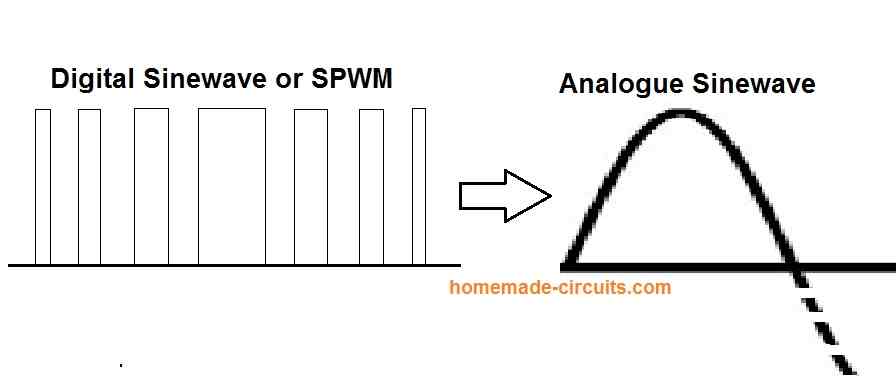
When this SPWM consisting of growing and shrinking pulse widths is applied to a transformer, the output from the transformer transforms this SPWM into an analogue equivalent which closely replicates an analogue sine waveform.
The easiest known method of generating a sinewaver PWM (SPWM), is by feeding a couple of exponentially varying signals to the input of an opamp for the required processing. Among the two input signals one needs to be much higher in its frequency compared to the other.
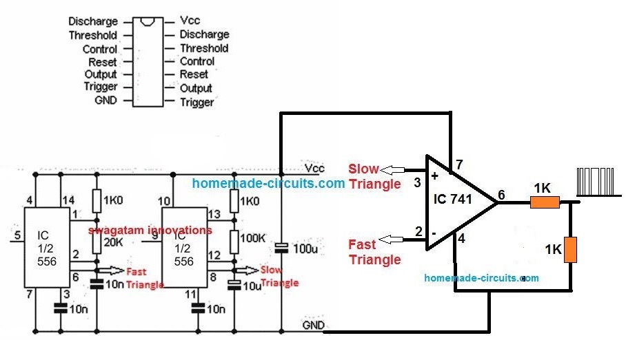
The IC 555 can also be used effectively for generating sine equivalent PWMs, by incorporating its built-in opamps and an R/C triangle ramp generator circuit.
The following discussion will help you to understand the entire procedure.
New hobbyists and even the professionals will now find it quite easy to understand regarding how sine wave PWMs (SPWM) are implemented by processing a couple of signals by using an opamp, let's figure it out with the help of the following diagram, and simulation.
Using two Input Signals
As mentioned in the previous section, the procedure involves the feeding of two exponentially varying waveforms to the inputs of an opamp.
Here the opamp is configured as a typical comparator, so we can assume that the opamp will instantly start comparing the instantaneous voltage levels of these two superimposed waveforms the moment these appear or are applied to its inputs.
In order to enable the opamp to implement the required sine wave PWMs correctly at its output, it's imperative that one of the signals has a much higher frequency than the other. The slower frequency here is the one which is supposed to be the sample sine wave which needs to be imitated (replicated) by the PWMs.
Ideally, both the signals should be sinewaves (one with a higher frequency than the other), however the same can be also implemented by incorporating a triangle wave (high frequency) and a sine wave (sample wave with low frequency).
As can be seen in the following images, the high frequency signal is invariably applied to the inverting input (-) of the opamp, while the other slower sinewave is applied to the non-inverting (+) input of the opamp.
In a worst case scenario, both the signals can be triangle waves with the recommended frequency levels as discussed above. Still that would help you to achieve a reasonably good sinewave equivalent PWM.
The signal with the higher frequency is termed as the carrier signal, while the slower sample signal is called the modulating input.
Creating an SPWM with Triangle wave and Sinewave
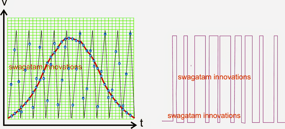
Referring to the figure above, we can clearly visualize through plotted points the various coinciding or overlapping voltage points of the two signals over a given time span.
The horizontal axis signifies the time period of the waveform, while the vertical axis indicates the voltage levels of the two simultaneously running, superimposed waveform.
The figure informs us regarding how the opamp would respond to the shown coinciding instantaneous voltage levels of the two waveforms and produce a correspondingly varying sine wave PWM at its output.
The procedure is actually not so difficult to imagine. The opamp simply compares the fast triangle wave's varying instantaneous voltage levels with the relatively much slower sinewave (this can also be a triangle wave), and checks the instances during which the triangle waveform voltage may be lower than the sine wave voltage and responds by instantly creating high logic at its outputs.
This is sustained as long as the triangle wave potential continues to be below the sine wave potential, and the moment the sine wave potential is detected to be lower than the instantaneous triangle wave potential, the outputs reverts with a low and sustains until the situation reverts.
This continuous comparison of the instantaneous potential levels of the two superimposed waveforms over the two inputs of the opamps results in the creating of the correspondingly varying PWMs which may be exactly the replication of the sine waveform applied on the non-inverting input of the opamp.
Opamp Processioning the SPWM
The following image shows the slo-mo simulation of the above operation:
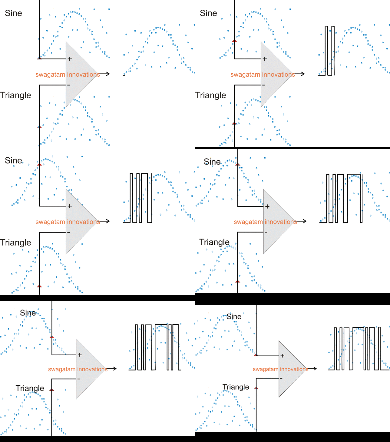
Here we can witness the above explanation being implemented practically, and this is quite how the opamp would be executing the same (although at a much fater rate, in ms).
The upper figure shows a slightly more accurate SPWM depiction than the second scrolling diagram, this is because in the first figure I had the comfort of the graph layout in the background whereas in the second simulated diagram I had to plot the same without the help of the graph coordinates, therefore I might have missed a few of the coinciding points and therefore the outputs looks a little inaccurate compared to the first one.
Nevertheless, the operation is quite evident and distinctly brings out how an opamp is supposed to process a PWM sine wave by comparing two simultaneously varying signals at its inputs as explained in the previous sections.
Actually an opamp would process the sine wave PWMs much more accurately than the above shown simulation, may be a 100 times better, producing a extremely uniform and well dimensioned PWMs corresponding to the fed sample. sinewave.
Circuit Diagram

Questions & Answers
Hi – Love your circuits. I need a soft-start circuit to power a 12 volt dc motor which draws up to 50Amp. peak. (I guess if it is overloaded it could draw more, so perhaps needs an overload shut-off).
I am contemplating using an Arduino to drive some mosFets in parallel, by providing a variable width PWM that rises from about 8 volts to full on over about 1.5 seconds.
I thought of using a 555 instead of an Arduino, and driving terminal 5 with an RC circuit to raise the threshold voltage up to its maximum, so that the On-time increases from about 80% to always on over about 1.5 seconds. Set the 555 to oscillate at about 1Kc to start. Do you have a circuit that might do that?
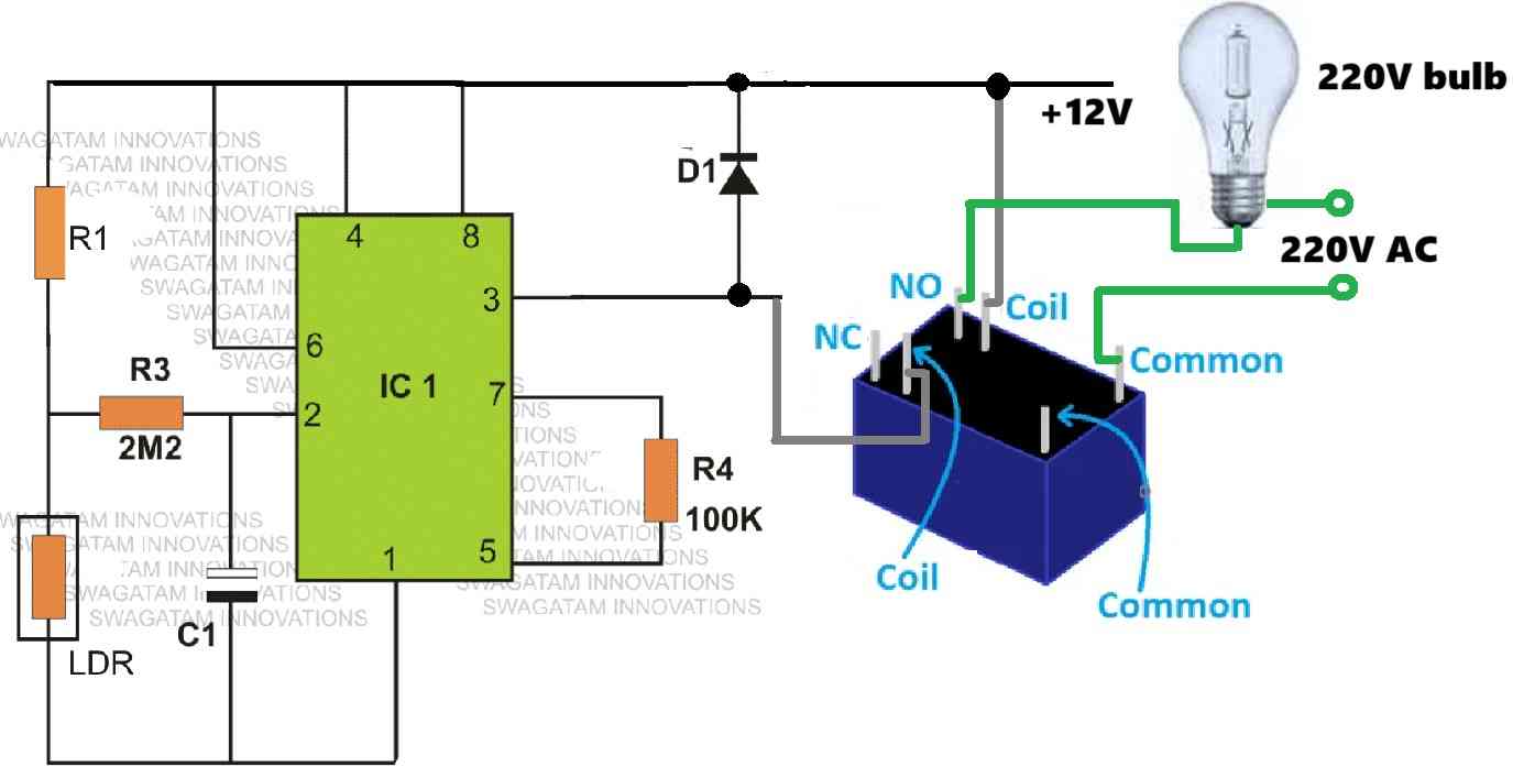
Hi, thanks for your kind feedback! Yes, Arduino and 555 both can be used to fulfil your requirement, but 555 would be much easier and cheaper compared to an Arduino alternative. Below given is a 555 based design having both, over current protection and soft start features. Let me know how it works for your application:

Thanks for your fantastic reply. I don’t know what time zone you are in but your response was ultra fast. I love the circuit, using the increasing capacitor voltage on the pin 5 control pin, and the transistor overcurrent protection. The 555’s are a remarkably versatile chip for lots of things. I forgot to mention that it has to be high-side switched. I could use a P-channel MosFet with a transistor for level shifting unless you have a better idea. Is there any potential problem with using several MosFets in parallel to get a better current rating? I also didn’t mention, that it is to drive a starter-generatior as used on a lot of mowers, golf-buggies etc., but to start vintage/veteran car engines which didn’t have starter motors. – low compression but lots of inertia – using much geared down drive with a belt around the flywheel. They work well, but hit too hard and slip the belts unless they are under very high tension. They tolerate the high revs when the engine is running, but the high belt tension doesn’t do their front bearing a lot of good. That is why I want a soft start. The high side switching is because the battery system is often earthed to the chassis. Once these systems start, as soon as they rev up a bit, they become a generator – so they generate more than the 12 volt battery voltage. This would mean that they would feed back to the battery through the intrinsic MosFet diode. I assume i could add a more high-powered reverse diode across the MosFet to carry some of this reverse current to protect the MosFet in case someone holds the start button on too long.
It’s my pleasure! I am located in India!
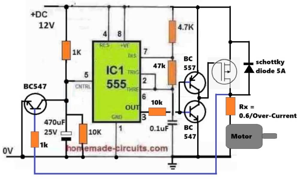
Right, if the load is ground based and needs its one terminal to be directly linked with ground, then a level shifter becomes the only option, along with a P-channel MOSFET.
You can definitely use a few these P-Channel MOSFETs in parallel, which would also avoid adding extra diodes across their drain/source terminals. Using parallel MOSFFETs is also advisable since P-channel MOSFETs tend to have relatively high RDSon causing high dissipation, and adding a few of them in parallel could simply prevent this situation. Nevertheless you can still put a diode across them, if needed.
I have attached the diagram below. It is also possible to avoid the extra NPN/PNP BJTs and instead hook up the MOSFFET gate directly with the 555 pin#3, simply by swapping the 470uF/10k, with the top 1k…meaning the 1k now comes down towards the ground rail, and the 470uF/10k goes up towards the positive rail side.
Sir, my question is where is pin5 and pin 9 of the ic 556 will be connected?
Thanks
Joseph, pin#5 and pin#9 can remain unconnected or open.
Thank you sir, I now understand
Merci beaucoup mille fois pour l’amour de t’aider les autres.
You are welcome!
Hi dear friend. I need a 115 volt ac power supply with variable frequency that i can change the frequency from 10 to 500 Hrz..
I have a 24V DC 5A power supply and a 240V AC 50Hz power supply, please help me to design and build this circuit. Thank you. Email me the circuit help me to design
Hi Fermaz, You can try the circuit design shown below. You will need a small transformer for converting the DC into AC:
I really appreciate everything you have been doing here. Pls sir, my major problem now is linking/connecting the circuits/diagrams of both techniques with the other parts of the inverter. Can you pls assist me with that?
Which circuit do you want to link?
I got a clearer picture after reading through your article titled” 3 high power sinewave inverter”. You’re the best. much love for showing us this love.
Can you pls present a transformerless and a transformer base sine wave inverter circuit for a solar powered inverters that can also charge the battery bank. Best regard.
Thank you very much, actually I already have all those circuits posted in this blog. You just have to search them using the search box above, you will be able to find them.
Is it correct to connect the main output of the charge controller (load) to the main output of the SG3525 waveform converter?
I have read through some related articles of yours and I have these few questions to ask: 1. How can I incorporate the solar charge controller in your article titled “solar charge controller for 100Ah battery” into the upgraded spwm circuit in your article titled “3 high power SG3525 pure sinewave inverter circuit”?
2. How can I upgrade the charge controller to work efficiently with a higher short circuit amps eg. 80amps, 12 to 15 high powered solar panels of eg. 600w, 45v connected in series or parallel. I.e, improving the total input solar array wattage, voltage and amperage.
You will have to connect the charger output across the battery terminals through a 2-way switch so that you are able to keep the inverter switched OFF while your battery is charging and switch ON the inverter when the battery is fully charged.
I apologize for too the much questions. Pls to be cleared with this statement, can you also let me have a rough sketch of what you mean by the above statement?
In the circuit shown in the following article, you can connect the “LOAD” terminals across the inverter battery terminals, and allow the battery to charge. While the inverter battery is charging do not switch ON the inverter, keep it switched OFF. Once the battery is fully charged then you can switch ON the inverter.
https://www.homemade-circuits.com/solar-charge-controller-for-100-ah-battery/
Mr swag thanks for your innovative post I tried out this circuit it worked out fine high pulses set at 405hz and low from Osc output I got a non flickering wattage at 51.2hz frequency but are there any other other options for spwm like with transistors or other components
Thank you Ifeanyichukwu,
An opamp circuit is much easier to build, if transistors were used, it would require at least 20 transistors to replicate the function, so it is not a feasible idea.
The out put of the spwm is showing 400Hz instead of 50Hz why and how can that be corrected
The SPWM will not be 50 Hz it will be equal to the fast triangle wave frequency
How do I converter it back to 50Hz
When to integrate the SWPM with an inverter with an output capacitor, the frequency will finally become 50 Hz.
Sir I also noticed that the duty cycle is not 50% kindly explain how to get 50% duty cycle and also how to get 50Hz frequency because I want to use it on H-bridge inverter of 5000kva
Jboy,
The 50 Hz slow triangle will need to be derived from Ct pin the inverter IC. All inverter ICs will have a Ct pin and Rt pinout. If these Rt and Ct are adjusted for 50% duty cycle and 50Hz frequency then the output of the op amp will generate sets of 50Hz SPWMs, with each SPWM set having 300Hz or 400Hz frequency.
These two sets of 300/400Hz SPWMs will chop the external mosfets gates at the rate of 50 Hz each to generate a 50 Hertz alternating AC cycles at the output of the transformer. But still these 50 HZ AC cycles will be composed of 300/400 Hz SPWM frequencies which will need to be eliminated by adding a 3uF/400V filter capacitor at the output of the transformer.
For more information you can go thrugh the following article:
https://www.homemade-circuits.com/sg3525-pure-sinewave-inverter-circuit/
Good explanation but the example you gave is half bridge inverter I have sg3524 which I I use an rc filter to get 50Hz triangular wave and the 400Hz triangular wave I generated with NE555 timer and also did an RC network to get the triangular wave now the two out puts are showing 400Hz but some of the pulse are in phase not completely out of phase with the upper frequency and I freed it to ir2110 gate driver IC the out put from Ir2110 is not stable and one phase is oscillating while the other phase is not please I want to use it to drive the inverter in H-bridge mode I direction on how to achieve that.
Please see the second diagram from the following article. It shows how to configure an SPWM circuit with a full bridge inverter IC:
https://www.homemade-circuits.com/5kva-transformerless-inverter-circuit/
Hi sir
can we make this SPWM circuit to alternate (ie Q and Q”) so that we can just linked the two output to the BJT without thinking of chopping any other existing PWM signals from another oscillator IC.
Hi Emmanuel,
yes that’s possible. I already have a related circuit using Arduino. You can find the circuit in the following link:
https://www.homemade-circuits.com/arduino-pure-sine-wave-inverter-circuit/
Hi swagatam
i know we can achieve that using Arduino but I was talking about how we can alternate this particular SPWM Generator circuit.
Without an Arduino, such a circuit can be very big and complex. The chopping concept would be much easier instead. So there are two easy options, either use the chopping concept or use the Arduino, anything else can be unnecessarily a lot more complex.
The complexity would be because of the synchronization issue of the SPWM for each cycle.
Alright sir
Dear Swagatam
What will happen if the inverting pin of the opamp is fed with the fast triangle wave and the non inverting is fed with a 50 Hz square wave, will we achieve the same spwm signal at the output of the opamp
Hi Richard,
In that case the output will be reversed. The PWM will start with a broadest pulse and will narrow down towards the center of the waveform.
Can such a signal be classed as an spwm or a modified square wave, which is witch sir?
It is SPWM…
Thanks for your assistance
Thanks a lot for you nippy reply,one more thing sir,must the higher frequency be fixed at 200hz or it must be varied?due to lack of oscilloscope,or at around what frequency must it be set so as to get the sine wave signal?
You are welcome Eniola. Without an oscilloscope the SPWM project cannot be accomplished. Yes it must be around 200 Hz otherwise your iron core transformer will start getting hot
Hi sir, the above article showed that the inverting pin should be connected to the fast frequency (pin2) while non inverting should be connected to low frequency, but in one of your article I read it was of lm742 opamp, fast frequency was connected to pin2 while slow frequency was connected pin 3.which one is correct ?or it can it connected anyhow?
Hi Eniola, the information provided in the above article is the correct one.