This article explains an interesting topic, how to convert your computer UPS into home UPS. If you own a desktop computer, you may have a UPS that can power your computer for 10-15 minutes after power failure.
Using an UPS
The purpose of the UPS is to save your work and shutdown your computer properly to avoid potential data loss and hardware loss such as Hard disk of your computer.
Most of us always underestimate the potential of the computer UPS that sitting beside your computer. The average computer UPS can deliver around 600VA, which is enough to power your low power appliances such as fan, tube light, computer, television, etc.
If you own more powerful UPS such as 1KVA you can power your home appliances more.
So how much can my computer UPS can provide? 600VA means the apparent power, but the real power is 60% of specified value. In other words it provides 60% of the VA rating.
For example:
If you have 600VA UPS then 600VA x 0.6 = 360W maximum output.
If you have a 1KVA UPS then 1000VA x 0.6 = 600W maximum output.
If my computer UPS can provide this much power, then why computer UPS only power 10-15 min?
This is because most of the computer UPS is only powered by 12V 7AH battery which is sitting inside the UPS.
To increase its backup time we need to connect several numbers of batteries with same specifications in parallel. The motto of this article is to make a cost effective home UPS from a computer UPS.
The procedure I have explained in this article is not suitable for beginners in electronics.
Block Diagram:
Circuit Operation
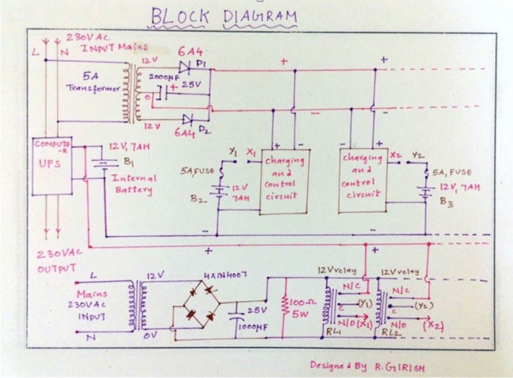
The whole UPS consists of an internal battery and several external batteries, which are crucial part of the UPS. The internal battery which is charged by internal circuitry of the UPS.
No external battery must be connected to charging circuitry during charging period. This is because the UPS is only capable of charging single SLA battery.
Exceeding more than one may overload the charging circuit and may lead to physical damage to UPS such as fried circuitry or may even cause fire. This is exactly opposite during discharge. All the batteries are connected in parallel including internal battery, injecting the power to UPS.
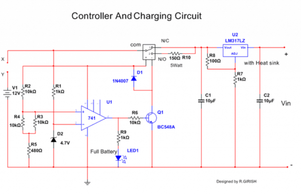
The external charging circuit consists of voltage regulator LM317 and op-amp comparator circuit for full battery cut-off. The voltage regulator gives out 13.75v for charging which is healthy amount of voltage for charging all kind of 12V SLA batteries.
When the battery reaches full battery voltage, relay cut-off the batteries from charging circuit and gives float charging to the battery via 150 ohm/5 WATT current limiting resistor. The relay triggered by op-amp comparator circuit.
There are two transformer one for charging which is 5A or more, the other transformer (500mA) for sensing the presence or absence of mains power.
If the mains are present relays are activated and connected to charger. If mains are absent relays are deactivated and batteries are connected to UPS. The 5A charging transformer may be replaced with SMPS.
The 100 ohm/5 watt resistor for quick discharge of 1000uf capacitor, so that relay can be deactivated instantly during power failure.
During power failure all the batteries connect automatically in parallel powering the UPS. When the batteries are at low state the UPS automatically disconnect its batteries and shutoff itself.
There is always low battery cut-off circuitry in the UPS. Most of the computer UPS gives out modified sine wave during power failure, and mains sine wave during normal state. This is suitable for most of home appliances.
WARNINGS:
1) Do not omit the internal battery, this plays an important role in giving uninterrupted power output and UPS circuitry gets unstable without the internal battery.
2) It is not recommended to connect more than 5 external batteries.
3) Do not connect this UPS to mains as what we do when we have genuine manufactured home UPS [IMPORTANT].
4) Use a branded computer UPS to proceed this project.
5) Never overload the UPS during normal/backup state.
6) Make sure that all internal and external batteries are with same capacity (AH) and age.
7) Do not connect any inductive loads other than table fan.
8) Place the whole setup at well ventilated area and don’t allow water to contact the setup.
9) Disconnect the gadgets immediately if you found misbehaving.
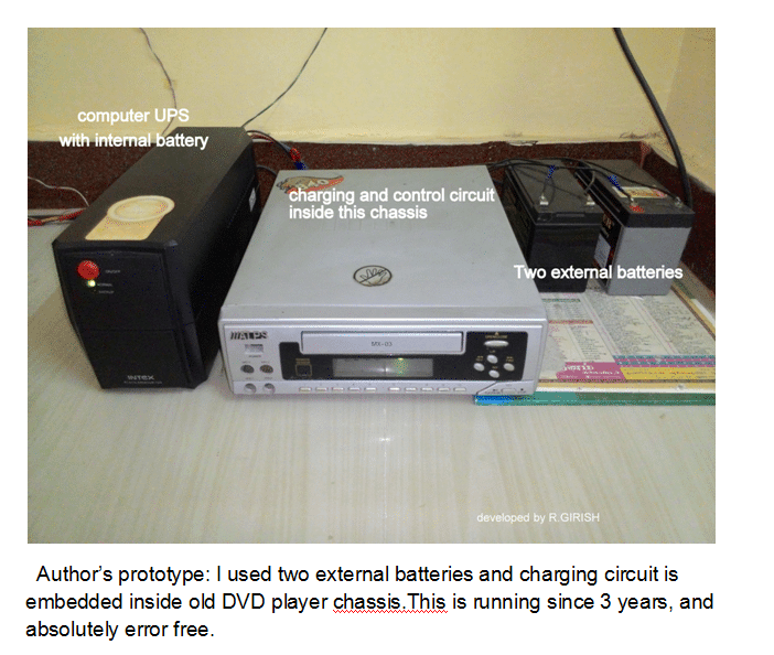
Author’s prototype
which shows how he could convert his computer UPS to home UPS:
I used two external batteries and charging circuit is embedded inside old DVD player chassis.This is running since 3 years, and absolutely error free.



Questions & Answers
Very useful. Some circuit diagram not showing.
Thank you, can you please check it now…
Hi,Can you send here full simulation of ups circuit kindly.
Sorry I do not have the simulation of the circuit with me right now..
hi sir , my ups 650va which gives about 300 watt . if i add another external battery same as internal will it give 600 watt power? and what procedure i should follow to do that?
Hi Shahoriyar, if your UPS transformer and the mosfets are rated at 650 VA and it is producing 300 watt only because of low power battery, then surely you can add an external battery in parallel to increase the capacity of the UPS to 650 VA. Use another battery having exactly the same rating as the existing one and put both the batteries in parallel.
Good day sir please sir How can i increase the watt of small blue gate ups
HI SIR, CAN USE MY COMPUTER UPS IS TO CHARGE 35AH 12 V BATTERY, HOW MUCH TIME TO TAKE THE BATTERY FULLY CHARGE, THE CHARGING AMPERE RATE OF UPS IS OK FOR THE 35AH 12 V BATTERY, PLEASE ADIVICE….
Hi Mohammad, It will depend on the charging current specs of the UPS, please specify the maximum output current from the UPS charger?
Good day Sir, how can I convert my mercury ups, model classic600 pro to inverter. The input/output voltage of the ups is 220/220VAC while the frequency is 50/60.
Which battery do you use for the UPS presently?
sir by mistake ups connection was given to 0.75 hp water pump at my residence after some time pump was tripped now ups is not working please tell what best to be done for this problem .
Muneer, did you check the fuse of your UPS?
Sir i have a dout ups 600VA……… power 360W………voltage 230v…… 12V 7.5Ah battry normaly using if i increased the battry to 12v 150Ah is it work????
Mathew, if you use a 12V 7.5Ah battery to power a 300 watt load, your battery will get damaged permanently and quickly. A 12V 150 Ah will work OK…
higher levels of Ah doesn’t matter as long as voltage is correctly matching.
Good job
My ups always shut down when the battery is drain to 10v. What can i do to extend it?
Your UPS is doing the correct thing, in fact it should shut down at 11V.
hii, can we use more power packed 18650 battery cells in the old computer ups to power up. I surely think modifications as mentioned by you may be required, can u suggest, if we can then we can have lot of backup in the small space of the ups casing itself. kindly suggest
Thanks GR and Ram for such useful data,
Please let me know, what is the least rating of battery which can be used with UPS , as I got the idea that UPS charging circuit is not strong enough to charge high rating battery like 150 AH.
Thanks
Sir please let me know how can i strengthen the charging circuit of ups to charge 70Ah batterry with smps inplace of inbuild charging circuit.
I want to make it like inbuild means it charges battery as in orginal case.
Wasim, I have not yet studied the above article, however I can tell you the universal rule for charging and upgrading any form of battery charging system.
For charging higher AH batteries you will have to upgrade the current (amp) input to the battery through a current control circuit designed to limit current at approximately 1/10th battery AH value (for lead acid batts), for your 70AH lead acid battery the controller must be tuned to produce 7 to 10AH current.
This battery can be used for a longer backup with the UPS or inverter, but make sure the UPS/inverter is also current controlled so that a short circuit or overload at the output does not burn the internal devices.
If you have any specific question you can ask, I’ll try to answer.
Why we should not use inductiv load on computer ups more then table fan , why we can't run silling fan on computer ups and why regular inverter can handle that load ?? Plz explain more about point 7 of warning list ??
because inveters are usually more powerful and able to sustain the higher watt load such as a ceiling fan
Lov dis .i do see dis stuff on d net but i thought ups timing is by some software modifications. But seeing it makes me blv it.i wl a usp but i want to use a 75amp battery can i just increase d charge current with transistors let say 2sc5200.tnx
you can use the following software to find an approximate figure
https://www.homemade-circuits.com/p/battery-calculator.html
Tnx for d reply.d author of dis post used 21ah 12volt battery in total. If i may ask how long is d backup time for dat battery amp
You can upgrade the charger section to 10amp and then use your preferred battery…the UPS output section will also need to be upgraded suitably for operating higher wattage loads
Hi sir your topic was so clear, but i have a doubt that can we improve the SMPS as wells as transformer to replace the smallwr battery with higher capacity one?
Thanks Sikkender, yes that's possible..
hi mr.Swagatam
sorry if this might be out of topic, but yesterday a friend gave me a used 2KVA home UPS(pascal 2000Hf, i already google for the manual but pity i cant found one for this type) with no internal battery, from what my friend recall its using 8 battery for backup but he didn't remember the connection if its in series or parallel, so i measure the UPS wire that goes to the batteries and it gave me about 110v. its a big help if u can tell me how i supposed to connect the batteries(in series or parallel ?) since i already bought them, once more Thanks in advance
may thanks for fast reply, now its working fine 😀
Hi Peter,
If you are sure regarding the 110V spec, then naturally many smaller batteries will need to be connected in series since a single 110V battery is not generally available in the market.
If the 100V is the charging voltage then probably you could employ 8nos of 12V batts in series with it.
Oh that means I need to short my transformer secondary through dmm in ammeter mode right???… The current value what I get from this state is considered as maximum rated current ???
yes that's right, and that's why you shouldn't keep it connected for more than 2, 3 seconds, otherwise you could see your meter smoking.
Sir, do you know the rating of the computer ups transformer???? My frnd gave one transformer for me its taken from computer ups but they didn't mentioned the rating of a transformer….say some average rating sir
you can connect the DMM directly across the secondary winding for measuring the current….make sure to keep the DMM in the 20amp or 10amp "AC" range, and do not exceed the procedure more than 2, 3 seconds.
OK sir,voltage can be easily measurable but how can I measure the current without loading transformer. Even if I get a load such battery. How can I estimate the allowable current to the load.suggest some techniques sir…thanks for fast reply
Vijay, the specification can be different for different UPS, it cannot be a universal fixed value…so would be difficult to judge.
however you can confirm it with a meter by the connecting the primary with AC mains, and by measuring the output V and amp accordingly with a digital meter.
Hi keiichii,
If your UPS intakes maximum current of 6 Amps, it does't mean that it charges your battery at 6 amp , as you stated on previous comments. The 6 amps is for your connected appliances load and also for the battery.
For 12V 7ah battery the charging current must not exceed 2 Amps , so the on-board charger don't supply current more than that.
The 6 amp is not the transformer's specification.
Regards.
I see.. it means transformer does. 2 in 1 (for load and battery). Ok sir.. thanks. I will use this UPS for dicharge with bigger battery and charge the battery separately.
Hi keiichii,
you can charge with your LM317 charger, make sure it can deliver enough current to the battery. Also add a full battery auto cut-off to your charger, so that you won't overcharge the battery.
Can you please elaborate,how your UPS can deliver 6 amps for the battery.(any thing specified on the UPS?).
@girish…Hi sir..the UPS states on its back that it has input of 220v~, 50hz 6.0 amps max (from wall outlet to the UPS). And output of 220~ 3.6amps (from UPS to your Appliances load)
Does the 6amp means transformer sir?
Hi sir. My UPS have 6amp built.in charger…. is this enough? If not. I will charge it seperately. I have LM317 adj. Voltage regulator with MJE2955 for current booster.. is this ok to charge SLA battery sir?
Ok sir i wont charge it using the UPS if the 6Amps is not enough….
Thank you for you recommendation.
Hi Keiichii,
You can use higher capacity battery to UPS, only during discharge process . The on-board charger in the UPS is not powerful enough to charge higher capacity batteries,there is risk of over-loading the on-board charger. so, this is not recommended.
if you really want to connect higher capacity battery, charge it separately and disconnect the UPS from AC mains during back-up mode. Check for unusual heating or any abnormalities during first test.
Regards.