In this post I have explained about a unique 8x overunity circuit quite resembling a joule thief design which was created by one of the noted researcher Professor Steven E. Jones while experimenting with a simple overunity concept.
8x more Output from a Simple Joule Thief Circuit
While developing this overunity circuit he was amazed to see an 8 fold or 8x improvement in the power output, which simply indicated an 8 times more output being produced by his circuit, compared to the input supply power.

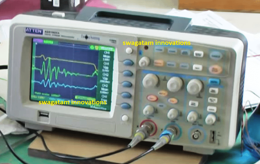
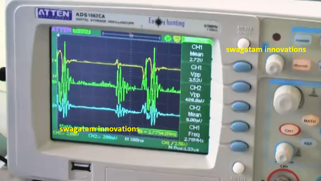
The results were distinctly evident on the oscilloscope screen which he used to verify the test results.
Mr. Steven E. Jones is an American physicist who particularly became popular for his intense research on muon-catalyzed fusion
While trying to develop a simple overunity theory he could discover this unique 8x overunity effect in his special joule thief circuit, using the advanced Tektronix oscilloscope, which made his finding look even more credible.
When asked from where the 8x free energy was coming from, professor said "I don't know where the energy is coming from, but it's coming from somewhere," and he himself seemed interested in solving it through other researchers.
During the course of the experiment, to be precisely sure about the working ability of the circuit, he kept it running overnight for 9 hours. In his prototype an LED was used as the load and a AAA cell, as the power supply.
The results were undoubtedly confirmed when he found that even after nine hours of continuous operation, the LED continued to remain illuminated brightly, yet the charge in the cell had hardly depleted. Without his circuit the cell would have easily gotten empty and the LED extinguished long before.
Although we are discussing just a fraction of milliwatts here, it's a good start and enough to prove the a substantial 8x overunity.
Circuit Diagram
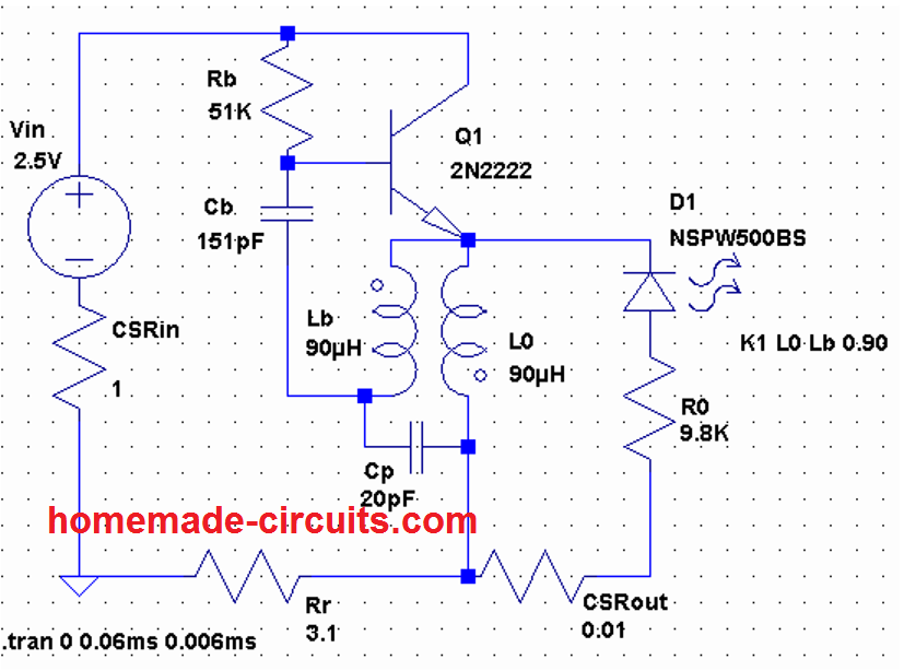
The circuit designed by Steve can be seen in the above figure, which is a modified variant of a joule thief circuit based on "blocking oscillator" principle.
In this mode, an LC network can be seen operating with the base of the BJT which you usually won't find in regular blocking oscillator designs. Professor Steven names this stage as the "boost resonator" since this stage resonates at a particular frequency and also becomes responsible for boosting the output and generating the overunity effect.
According to Mr. Steve, he could also develop a method of fine-tuning the efficiency of the circuit to a level where the input consumption virtually reaches to almost nothing.
He further revealed that the crucial element of the circuit was the inductor in the form of a torroid, specially devised by him. Although the construction of this torroidal inductor is easy, and could be hand wound, it lets you witness some amazing results.
In his design the following parts were used
Rb = 2k, 1/4 watt
Ro = 9.8k,
Rr = 3.1k,
T1 = MPS2222
Cb = 151pF,
D = LED red,
Power supply: 2V DC from a couple of rechargeable AA cells.
Both CSR = 1 ohm 1/4 watt (current sensing resistors)
Making the Inductor Coil

The inductor was constructed with the following details:
L-B, L-O = 9 turns using bifilar winding
Core = Torroid 1"OD, 1/2"ID, 7/16" tall
Inductance value: approximately 90uH each
Practical Test Results
Here's the original voice transcript of professor Steven, illustrating the test results on his state-of-the-art tektronix oscilloscope.
"Basically, the power is coming from two AA rechargeable cells and little 1 ohms resistors in series with the battery, so I measure the input voltage and the input current, the voltage drop across the 1 ohm resistor and that gives me the input power, multiplying the input voltage times the input current, I get the instantaneous power that’s actually the green trace here, the yellow trace being the input voltage, the blue is the current, and the green is the output. The frequency is around 2.8MHz......"
Proof of 8X Overunity
The above outstanding research by Dr. Steven, finally proves that overunity is actually possible through some means even if it remains mysteriously untraceable.


Comments
So a fraction of a milliwatt over 9 hrs. is not much in the line of power how close to some radio tower to get a milliwatt blead in charge do we need to be. not to get off subject what if there were a real big output device that could generate power 24/7 365 at lets say 25,000 watts or how about megawatt. Corinne Technical Design — EttCM Energy Technology. Washington State USA. let me show you how it done. Thanks.
This extra energy is coming from the ZPE energy field. It happens anyway, although unless you have resonance, it usually requires more energy being put in than what is coming out. John Bedini, Eric Dollard and OTHERS (Patrick Kelly, etc.) on the internet can give you more info.
Hi dear Swagatham, is it possible for someone build x8. Where input is 12v or more and output of 100w to 1kw, thanks.
Hi Kingpost, it may not be possible using the above explained overunity concept
Dear Swagatam,
The said circuit, if analysed may be works on the principle of parametric resonance. This type of energy production was studied by Russian academics Mandelstam and Papalexi “On the Parametric Excitation of Electric Oscillations – 1934 – NASA 1968.pdf ” among others in the early 30-es. In USA Wanlass put in production in the 60’s the Paraformer “US3403323_Electrical energy translating devices and regulators using the same”.
In the yearly 2000-s a Russian engineer developed the parametric machine of Mandelstam and Papalexi on solid state devices – transistors, transformers, SCR-s and for switching regulator used a blocking oscillator circuit. His patent has expired in 2012, but the whole machine fundamentals are described in details in his patent together with the math of operation. This patent was granted even though it was explored by the Committee for Pseudo Science at the Russian Academy of Science. The circuit is powered from its own output, and only for the start it uses a battery for less than a minute.
In case of interest I may prepare exact translation from Russian, not the one from Google AI.
I am not an electronic engineer, that is why would be glad to have some professional help to calculate the necessary components, based on the operation maths of the device provided in the patent documentation.
Waiting for comments and interest to make this technology open sourced.
Best regards
Glarus
glarus80@protonmail.com
p.s.: meanwhile I study at great speed and your page is one of the best ever I have found on the internet community. Thank you for this.
Thank you very much Dear Glarus, for your valuable inputs.
No problem, you can definitely share your translated document with me so that I can publish the same in this blog.
I am glad you are liking my posts, please keep up the good work!
If 8X more output was really being produced than the input, you could just connect the output to the input and use 1/8th of the output to power itself and the remaining 7/8ths to run the LED
Remove the battery, and the LED would run infinitely long. Obviously this wouldn’t happen so you’re just measuring incorrectly.
Hello Mr. Swagatam . The 8x Overunity Circuit can be used for AC current application. Thank you.
Hi Andras, I am sorry no, it is applicable only with DC inputs
I am building a circuit that uses a HC-SR501 PIR. The PIR requires a minimum of 4.5V. The rest of my circuit requires 3v-5v. The problem arises when the batteries get lower than 4.5V, then the PIR begins to not function properly. I could use a 6V battery pack and voltage regulator to protect my other components, but that takes up space. I was wondering if there is a way of boosting the battery power to the PIR so when my batteries get lower than 4.5 volts the PIR still sees more than 4.5V. This would make my batteries last longer before replacement.
you can try the following concept
https://www.homemade-circuits.com/1-watt-led-driver-using-joule-thief/
you can modify the collector side winding to adjust the output voltage for the circuit as required.
Hi dear Swagatham, I did not fully get the point….8x free energy….!!!!
Is this means, power source, say a AA dry cell will last 8 times than a normal Joule thief circuit.
I have already assembled many Joule thief circuits, that only consumes 12mA to 18mA from a single AA cell.
A blue LED continuously run 28days on a fresh AA cell.
If I modify my circuit like the above circuit, will my battery last eg.28days x 8=224days….?
Regards
Dear Anil, 8X refers to 8 times more than what you would get if you connected the LED directly with the battery…. not through a joule thief circuit.
you are already getting very high efficiency using a joule thief circuit, modifying it in the above manner could sightly improve the situation and keep the LED illuminated for some days more…