The post narrates an automatic Battery Bank charger circuit with an automatic over charge cut-off feature for operating with an electric car. The idea was requested by Mr. George.
Circuit Objectives and Requirements
- I'm George From Australia trying to convert small car into an electric car.
- The attached PDF show the configuration of lithium battery modules that make the full pack.
- Could be possible for you to suggest what sort of battery charger or configuration can I use too charge the pack.
- I have available 240 Volts or 415 Volts AC.
Battery Wiring Details
The Design
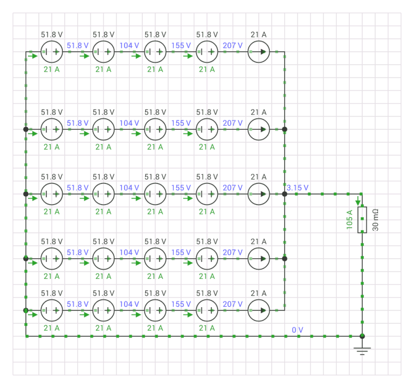
The above figure shows the Li-ion battery configuration arranged in series, parallel mode to generate a massive 210V at 80 Amps approximately.
To charge this relatively huge battery set up we need a controller which is able to control current as well as provide the required amount of volts to the pack for charging them efficiently.
The 240V AC source looks more appropriate, so this source could be used as the input for the mentioned purpose.
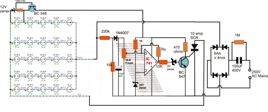
The next diagram shows the proposed 220V Li-ion Battery Module charger circuit, I have explained its functioning in detail with the following explanation:
Circuit Diagram
Circuit Functioning
The design is quite similar to one of the previous concepts regarding a high voltage battery charger circuit, except the relay section which is replaced with an thyristor here, and the inclusion of a high voltage dropping capacitor for an added safety.
The mains high current is suitably dropped by the reactance of the 100uF/400V non-polar capacitor to around 5amps which is applied to the battery bank via the indicated thyristor. This current can be increased to higher level by simply increasing the capacitance values of the shown 100uF/400V cap.
The thyristor or the SCR which is used as a switch in this design is held in the switched ON position as long as the associated BC547 at its gate is held switched OFF.
The BC547 base can be seen connected with an opamp output which is configured as a comparator.
As long as the output of the opamp is kept low the BC547 stays switched OFF, keeping the thyristor switched ON.
The above situation continuous to be in the activated state as long as the preset voltage level of the sensing input pin#3 of the IC remains below the reference level of the pin#2 of the IC.
Since pin#3 is hooked up to the battery positive (via a resistive network), it implies that the 10K preset at pin#3 is supposed to be adjusted such that at the full charge level of the battery the potential at pin#3 just surpasses the reference fixed potential at pin#2.
As soon as this happens the opamp output pin#6 instantly reverts its output from the initial logic low to a logic high, which consequently switches ON the BC547 and switches OFF the triac.
The battery charging is immediately stopped at this point.
Function of Hysteresis Resistor
The hysteresis resistor Rx connected across pin#6 and pin#3 of the IC makes sure that the opamp latches ON in this position at least for sometime until the battery voltage has discharged to some predetermined lower threshold level.
At this unsafe lower level the opamp yet again goes through a changeover and initiates the charging process by triggering a logic low at its output pin#6.
The difference between the full charge cut-off voltage and the low charge restoration voltage is proportional to the value of Rx, which could be found with some trial and error. Higher values will result in lower differences and vice versa
The potential divider network made by the indicated 220K and the 15K resistors ensures the required lower proportionately dropped voltage for the opamp pin#3, which should be not above the operating voltage of the opamp.
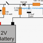
The operating supply voltage for the opamp at its pin#7 is acquired through a BJT emitter follower configuration connected across one of the end batteries associated wit the negative line of the battery pack.
For further queries regarding this 220V Li-Ion Battery bank charger circuit please feel free to usdethe comment box below.
DANGER: THE DESIGN EXPLAINED ABOVE IS NOT ISOLATED FROM THE AC MAINS LINE, THEREFORE IS EXTREMELY DANGEROUS TO TOUCH IN SWITCHED ON POSITION. PROCEED WITH CAUTION.


Comments
Hi Swagatam,
I think that a circuit like this is very good for my application with some modification (Charging Solar battery by diverting export energy to battery), as discussed earlier in another design I’m looking at controlling the current and voltage via an MCU 0-3.3VDC, voltage would be increased when balancing is required, current would be increased with export levels.
I also would be connecting to a 230vac supply which I can enable / disable depending on solar production via the MCU. In my instance I could use 5x 36V 50AH batteries in series, from the manufacturers data sheet charging info:
Discharge Cutoff Voltage 30 V
Recommended Charge Voltage 43.8 V
Charge Float Voltage Range 41.4 – 43.8 V
Recommended Charge CCCV ≤ 25 A to 43.8 V
I believe I have read it is best to charge the cells to around 80-85% capacity and then carryout a full charge that invokes balancing maybe once a month or when the BMS dictates requirement? Does this mean charging at around 41V per battery (205V) normally, and then switching to the higher charging voltage when balancing is required?
I can appreciate that with a circuit like this then an isolating transformer may be required.
Any help on design would be really appreciated as it would be nice to decide on buying batteries and building such a charger whilst we have the summer sun.
Hi ChrisF,
As I mentioned in one of my earlier replies, if things like MCU, balancing are involved then it is beyond the range of my expertise. My knowledge regarding these aspects is not good. I can only help with chargers for single batteries without MCU or balancing.
Hi Swagatam,
Thanks for your prompt reply, lets take the MCU out of the equation as I can handle that part. can you provide a modification to the circuit that will allow me to adjust charging current by receiving a 0-3.3vdc input from my MCU, same goes for charging voltage control.
Regards
Thank you ChrisF,
Still that looks difficult to me. Because translating a 0 to 3.3 V supply into a proportionately varying output current to the battery is not easy to achieve, I have no idea how to do that.
Please could you advise me if the 48v automatic battery charger be altered to charge a lion drill 18v battery.
throston
I can’t see any 48 V battery here
Hi.
Thank you for your prompt reply.
What I am looking for is a circuit to build a battery charger to charge an 18volt nicad drill battery.
Hope you can help.
throston
Hi.
Thank you very much for your help,you are very kind and helpful.
throston
You are welcome!
You can try the following concept
https://www.homemade-circuits.com/cordless-drill-battery-charger-circuit/
Hello,
Your schemes are looking very attractive, in my own case I’m looking to charge a Li-ion pack made of 11 elements in serial. Battery is about 300 What is design to power an e-bike with 36 V.
Problem is that charger for 10S battery packs are very common but for 11S this is not the same story …
Thanks,
Thanks Goujon, For your case there’s seems to be only one possible option, it is to change the charger with another one rated to charge a 36V pack, or you can modify the existing charger and try raising its output level by an additional 4.2V so that it becomes compatible to charge your 11 cell pack.
sir in the above circuit the input voltage is 240volt rectified AC wont it damage the back batteries or how is the 220volt batteries able to absorb the 240volt safely with out being damaged
Marvin, the full charge level of the battery bank id 257V, and moreover the 100uF capacitor will drop the current to a considerably lower level and allow safe charging
Thanks for quick reply sir but do you have an idea about the amount of amps Nigeria ac 220 line have
And sir how many amps can i get from a 5killowatt transformer
sorry I do not have any information about it…
sir i how many amps is the 240v two phase ac line capable of
sir if it is 300 to 400 amps how many (UF) of capacitor do i have to use or will have to eliminate the capacitor to charge a 200v high amperage battery of 2700amps lithium ion battery i want to get ride of the bulky 5kv stabilizer transformer i am using it heat up really quick
The mains current spec may be different depending on country and region specifications, however charging a 2700 Ah may not be recommended as it may cause a significant drop in the mains voltage. You can try charging the battery in parts.
moreover the capacitor will be too huge for carrying 270 amps, and the value may be impracticable.
sir can i use a contactor instead of the src
contactor may require start stop switches which can be difficult to configure with the circuit, instead you can use any higher rated SCR such as IRKT250 etc
i am planning to use a 5kva stabilizer transformer and 100amp alternator diod to make a 100amp bridge to charge the pack with 100amps.
yes you can use this concept, however the input 100uF capacitor can be eliminated if you are using a transformer…
can i use this to charge my 168v 1200amps lithium ion battery pack
Does this circuit also helps in stop charging when the battery is charged full??
yes it is fully automatic
The display is capable for voltage less than 5V sir since it has been taken from power bank.. I have asked that question because I need to evaluate the charging of that series combination with that display board.. Since the charging of individual batteries in the series combination takes place simultaneously, there would be a possibility for all the batteries to charge in an uniform way right ? That why i was planning to connect the display to any one of them ?
if my assumption is wrong can you briefly explain how individual batteries get charged while in series config. ?
the charging rate will depend on the instantaneous characteristics of the individual cells, and also their instantaneous discharge levels.
RT, that cannot be guaranteed, all cells might never have the exact same characteristics, and therefore might show slight differences in charge levels, especially when the cells are used ones and not new….you can assume the reading to be approximately equal to the average of the cells, but that cannot be a reliable method of determining the result
Sir I have 6 Samsung Li – Ion batteries taken from a Power bank.. Each cell is showing a voltage approx. 4.1 V under full charge condition. I need to use these 6 batteries in series to form a 24 V dc power supply which can operate maximum of 48 W load( say each battery can draw max. of 2.5 A ) .. This series combinatiob of the batteries will be fixed and no further alteration is advicable..
I have a suitable 25V power source to charge the battery.. also I have the digital display taken from the power bank which can show the battery charging percentage while charging..
My question is if I am connecting this led display parallel to any one of the batteries in that series combination, will it give an average or approximate charging level indication while charging ?
I want to use this display as the charging indicator. That is why I am asking this question to you.
And if that set up is possible which battery among the series combination will be most suitable to connect with the led display ? The top one, bottom one or the middle one ?
Hi RT, if you connect the display circuit with any one of the Li-ion cells, then it will show the charge level of that particular cell, not the average value of the whole series assembly. It's better to connect the display across the whole series end to end, that would provide you with the correct charge level of the unit.
could you please explain how you are getting a pulsating DC of 100Hz as the input is 250V 50Hz AC.
the bridge transforms both the positive and negative half cycles of the AC into full wave positive half cycles causing both the AC halves to appear on the positive side of the bridge supply, and thereby doubling the frequency from 50 to 100Hz.
Sir, could you tell me what is the function of 1N4007 diode and 10mf capacitor. And why are you reducing the current using 100mf capacitor. By using high current can't we charge the batteries quickly?
The supply to the scr/battery is 100Hz pulsating DC…so SCR will respond to the gate triggers.
connecting 220V mains directly with the battery is never recommended, you will have to use either a transformer or a capacitive limiter in between.
you can use a transformer, as you have already shown in your email request.
The battery has a rating of 80Ah,if my aim is to quick charge the battery cant i supply high current till the battery reaches 80% and then reduce the current to 5A for the safe operation of battery.
Also how are you turning the SCR off.The gate of SCR has no control over the SCR once its ON
Ajay, the 1N4007 and the 10uF are not important and can be removed,…but the 100uF/400V is important otherwise the full AC mains current would try to enter the battery bank and damage the batteries.