• Skip to main content
  • Skip to primary sidebar

Homemade Circuit Projects

Need circuit help? Post them in the comments! I've answered over 50,000!

Blog | Categories | About | Hire Me | Contact | Calculators-online
You are here: Home / Archives for 2013

Archives for 2013

10 Step Relay Selector Switch Circuit Diagram

Last Updated on January 17, 2025 by Swagatam 131 Comments

electronicselectorswitchcircuit

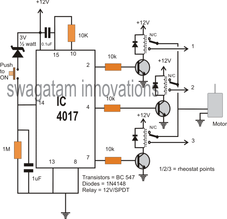
In this post I have explained a simple yet useful 10 step selector switch circuit which can be operated using a singe push-to-ON switch. In the following design the circuit is used as a 3 step, single push motor speed controller unit. The circuit was requested by Mr.Edalcor. Technical Specifications hi sir good day to to you, can you please design […]

Filed Under: Mini Projects Tagged With: Relay, Selector, Step, Switch

10 Band Graphic Equalizer Circuit Diagram

Last Updated on January 17, 2025 by Swagatam 131 Comments

10 band graphic equalizer circuit 1

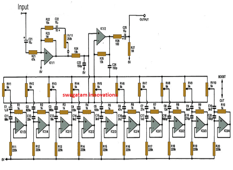
The proposed 10 band graphic equalizer circuit can be used in conjunction with any existing audio amplifier system to get an enhanced 10 stage audio processing, and customized tone control. The circuit can be easily converted to a 5 band graphic equalizer by simply eliminating 5 stages from the shown design The Circuit Concept A […]

Filed Under: Audio and Amplifier Projects Tagged With: Band, Equalizer, Graphic

1.5V to 12V DC Converter Circuit Diagram for LEDs

Last Updated on January 17, 2025 by Swagatam 31 Comments

FNKON0WH78T8LG3.LARGE

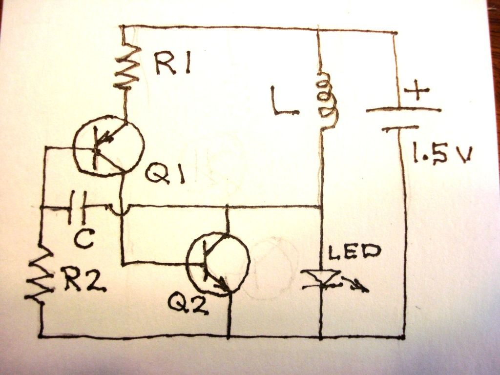
The post provides interesting information regarding the making of a 1.5V to 12V converter circuit using a couple of transistors and an inexpensive coil. The idea was requested by Mr. Keith. The Circuit Request I found your blog and have searched for an answer to my question but I’m just not finding it…. What I want to do […]

Filed Under: Power Supply Circuits Tagged With: 12V, Converter, DC, LEDs

1.25V to 120V Mains Adjustable Voltage Regulator Circuit Diagram

Last Updated on January 17, 2025 by Swagatam 35 Comments

1.25Vto120Vadjustablevariablepowersupllycircuit

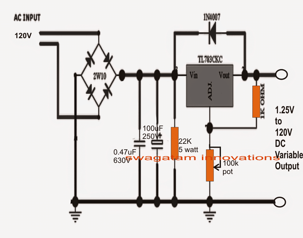
The TL783 is a variable three lead mains voltage regulator chip having an output range of 1.25 V to 125 V and a DMOS output transistor which is able to handle in excess of 700 mA current. High Voltage Specification It is specifically configured internally for working with high-voltage applications where ordinary bipolar voltage regulators […]

Filed Under: Power Supply Circuits Tagged With: 120V, 25V, Adjustable, Mains, Regulator, Voltage

1 to 10 minutes Timer Circuit Diagram

Last Updated on January 17, 2025 by Swagatam 26 Comments

Simple Frequency Counter Circuit Diagram

The post narrates a simple yet highly accurate adjustable 1 to 10 minute timer circuit with display. The idea was requested by one of the dedicated readers of this blog. Technical Specifications I am trying to build a circuit to help me with giving speeches. I have a bunch of parts already and I would […]

Filed Under: Timer and Delay Relay Tagged With: Minutes, Timer

0-300V Adjustable Transformerless Power Supply Circuit Diagram

Last Updated on January 17, 2025 by Swagatam 267 Comments

ZEROTO220300VVARIABLEPOWERSUPPLYCIRCUIT

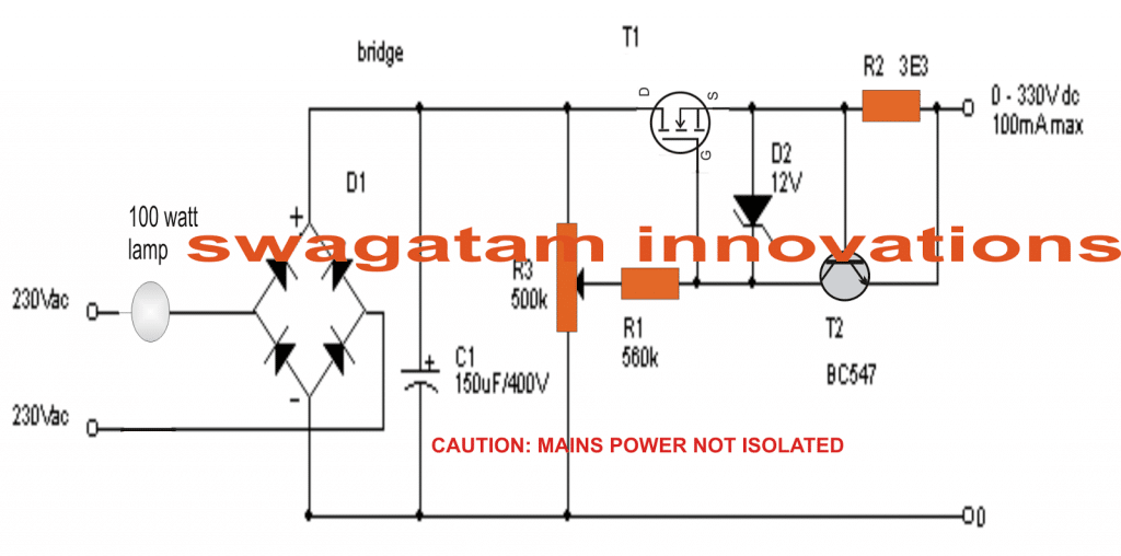
This simple MOSFET controlled transformerless power supply circuit can be used for delivering a continuously variable 0 to 300V DC output and a current control from 100 mA to 1 Amp. To protect against my high voltage research projects from going up in smoke permanently, I developed an easy circuit which is able to render […]

Filed Under: Power Supply Circuits Tagged With: 300V, Adjustable, Power, Supply, Transformerless

  • « Go to Previous Page
  • Page 1
  • Interim pages omitted …
  • Page 5
  • Page 6
  • Page 7
  • Page 8
  • Page 9
  • Interim pages omitted …
  • Page 27
  • Go to Next Page »

Primary Sidebar

circuit simulator image

Subscribe to get New Circuits in your Email

Categories

  • Arduino Projects (96)
  • Audio and Amplifier Projects (134)
  • Automation Projects (18)
  • Automobile Electronics (103)
  • Battery Charger Circuits (87)
  • Datasheets and Components (109)
  • Electronics Theory (149)
  • Energy from Magnets (27)
  • Games and Sports Projects (11)
  • Grid and 3-Phase (20)
  • Health related Projects (27)
  • Home Electrical Circuits (13)
  • Indicator Circuits (16)
  • Inverter Circuits (96)
  • Lamps and Lights (160)
  • Meters and Testers (72)
  • Mini Projects (28)
  • Motor Controller (68)
  • Oscillator Circuits (28)
  • Pets and Pests (15)
  • Power Supply Circuits (91)
  • Remote Control Circuits (50)
  • Renewable Energy (12)
  • Security and Alarm (64)
  • Sensors and Detectors (106)
  • SMPS and Converters (41)
  • Solar Controller Circuits (60)
  • Temperature Controllers (43)
  • Timer and Delay Relay (50)
  • Voltage Control and Protection (43)
  • Water Controller (37)
  • Wireless Circuits (31)

Other Links

  • Privacy Policy
  • Cookie Policy
  • Disclaimer
  • Copyright
  • Videos
  • Sitemap

People also Search

555 Circuits | 741 Circuits | LM324 Circuits | LM338 Circuits | 4017 Circuits | Ultrasonic Projects | SMPS Projects | Christmas Projects | MOSFETs | Radio Circuits | Laser Circuits | PIR Projects |

Social Profiles

  • Twitter
  • YouTube
  • Instagram
  • Pinterest
  • My Facebook-Page
  • Stack Exchange
  • Linkedin

Recent Comments

  • Swagatam on Simple SG3525 Sine Wave Inverter Circuit Explained
  • Swagatam on 220 V Slow Fade Bedside Lamp Circuit
  • Swagatam on Small Induction Heater for School Project
  • brian on Small Induction Heater for School Project
  • David on Simple SG3525 Sine Wave Inverter Circuit Explained

© 2026 · Swagatam Innovations