A relatively simple 1000 watt pure sine wave inverter circuit is explained here using a signal amplifier and a power transformer.
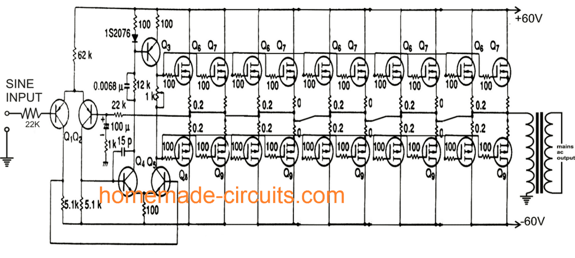
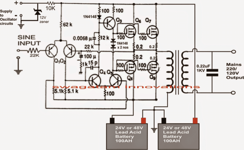
As can be seen in the first diagram below, the configuration is a simple mosfet based designed for amplifying current at +/-60 volts such that the connected transformer corresponds to generate the required 1kva output.
UPDATE:
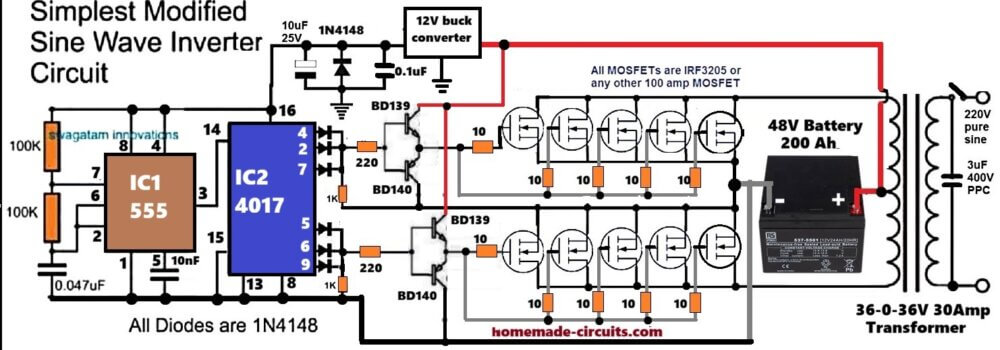
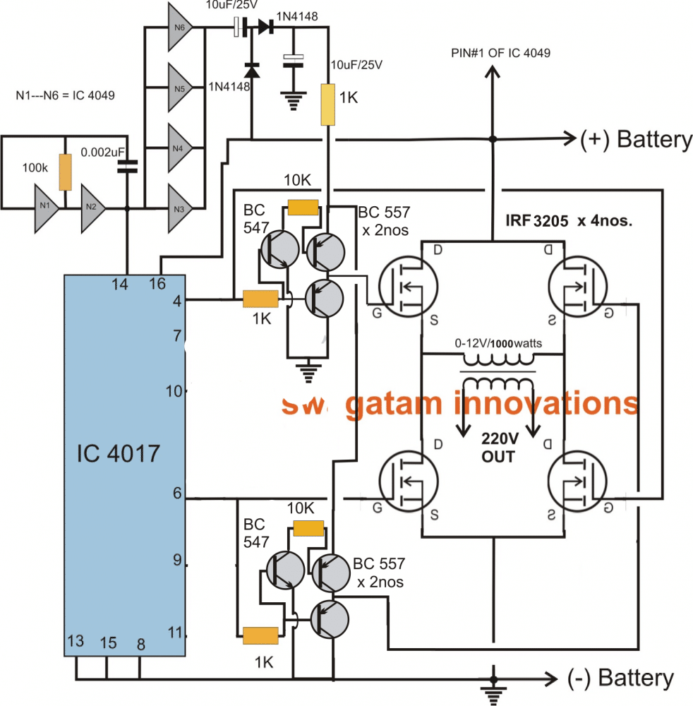
There's a much easier and efficient way of making a 1 kva inverter circuit using the following 4017 PWM version circuit. Since the PWM is created directly through the 4017 output, the PWMs are much accurate and the waveform is uniform and does not depend on any external adjustments.
The biggest advantage of using this circuit is that the output can be modified to almost a pure sine wave by adding a few PPC capacitors across the transformer output.
Here' the circuit which you can try:
Audio/Video Representation
Parts List
- Resistors
- All resistors are 1/4 watt 5% unless specified
- 100K = 2nos
- 100 ohm 1 watt = 1no
- 1K = 2no
- 10 ohm = 2no
- Capacitors
- 0.047uF ceramic or PPC = 1no
- 10nF ceramic or PPC = 1no
- 10uF/25V Electrolytic = 1no
- Semiconductors
- 1N4148 diodes = 7nos
- 12V/1 watt zener diode = 1no
- IRF3205 MOSFETs = 10nos
- Transformer 12-0-12V/220V/1kva
- Battery = 24V/500 Ah = 1no
The previous original article which is continued in the following paragraphs also discusses a 1000 watt inverter circuit, however, this circuit being a linear amplifier is not so efficient, and may result in a lot of dissipation.
I would recommend trying the above circuit, which will give you a 100% results quickly.
Remember, you must first try and confirm the working of the inverter using single MOSFETs on each channel. Once the working is confirmed then you can add more number of MOSFETs in parallel to upgrade the power capacity of the inverter to 1000 watts
Circuit Operation
Q1, Q2 forms the initial differential amplifier stage which appropriately raises the 1vpp sine signal at its input to a level which becomes suitable for initiating the driver stage made up of Q3, Q4, Q5.
This stage further raises the voltage such that it becomes sufficient for driving the mosfets.
The mosfets are also formed in the push pull format, which effectively shuffles the entire 60 volts across the transformer windings 50 times per second such that the output of the transformer generates the intended 1000 watts AC at the mains level.
Each pair is responsible for handling 100 watts of output, together all the 10 pairs dump 1000 watts into the transformer.
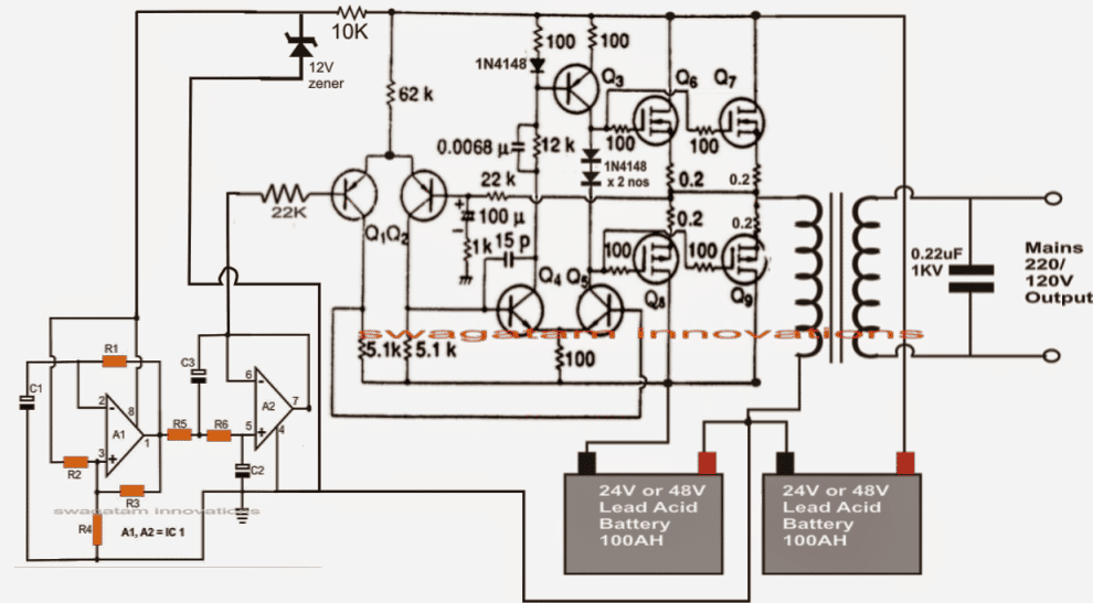
For acquiring the intended pure sine wave output, a suitable sine input is required which is fulfilled with the help of a simple sine wave generator circuit.
It is made up of a couple of opamps and a few other passive parts. It must be operated with voltages between 5 and 12. This voltage should be suitably derived from one of the batteries which are being incorporated for driving the inverter circuit.
The inverter is driven with voltages of +/-60 volts that amounts to 120 V DC.
This huge voltage level is obtained by putting 10 nos. of 12 volt batteries in series.
The Sinewave Generator Circuit
The below given diagram shows a simple sine wave generator circuit which may be used for driving the above inverter circuit, however since the output from this generator is exponential by nature, might cause a lot of heating of the mosfets.
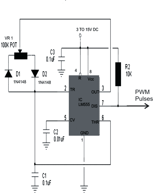
A better option would be to incorporate a PWM based circuit which would supply the above circuit with appropriately optimized PWM pulses equivalent to a standard sine signal.
The PWM circuit utilizing the IC555 has also been referred in the next diagram, which may be used for triggering the above 1000 watt inverter circuit.
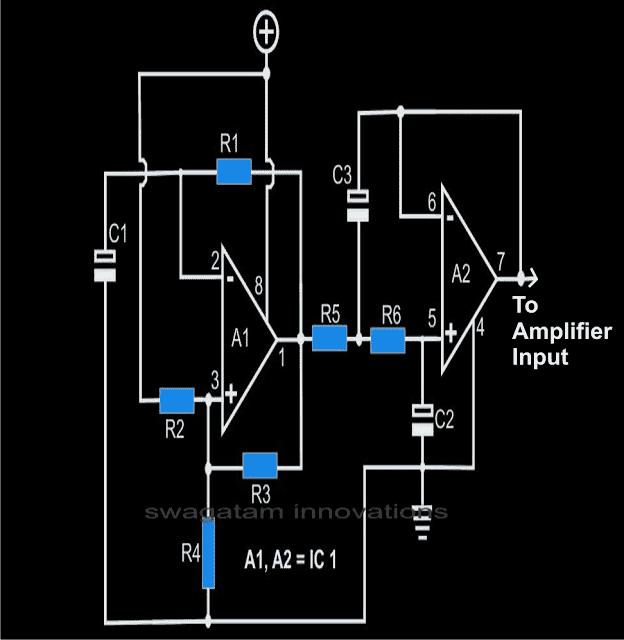
Parts List for the sine generator circuit
All resistors are 1/8 watts, 1%, MFR
R1 = 14K3 (12K1 for 60Hz),
R2, R3, R4, R7, R8 = 1K,
R5, R6 = 2K2 (1K9 for 60Hz),
R9 = 20K
C1, C2 = 1µF, TANT.
C3 = 2µF, TANT (TWO 1µF IN PARALLEL)
C4, C6, C7 = 2µ2/25V,
C5 = 100µ/50v,
C8 = 22µF/25V
A1, A2 = TL 072
Part List for Inverter
Q1, Q2 = BC556
Q3 = BD140
Q4, Q5 = BD139
All N-channel mosfet are = K1058
All P-channel mosfets are = J162
Transformer = 0-60V/1000 watts/output 110/220volts 50Hz/60Hz
The proposed 1 kva inverter discussed in the above sections can be much streamlined and reduced in size as given in the following design:
How to Connect Batteries
The diagram also shows the method of connecting the battery, and the supply connections for the sine wave or the PWM oscillator stages.
Here just four mosfets have been used which could be IRF4905 for the p-channel, and IRF2907 for n-channel.
Complete 1 kva inverter circuit design with 50 Hz sine oscillator
In the above section we have learned a full bridge design in which two batteries are involved for accomplishing the required 1kva output. Now let's investigate how a full bridge design could be constructed using 4 N channel mosfet and using a single battery.
The following section shows how a full-bridge 1 KVA inverter circuit can be built using, without incorporating complicated high side driver networks or chips.
Using Arduino
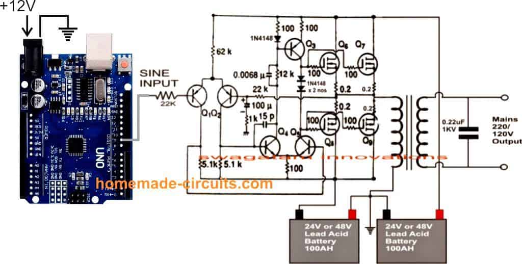
The above explained 1kva sinewave inverter circuit can be also driven through an Arduino for achieving almost a prefect sinewave output.
The complete Arduino based circuit diagram can be seen below:
Program Code is given below:
//code modified for improvement from http://forum.arduino.cc/index.php?topic=8563.0

//connect pin 9 -> 10k Ohm + (series with)100nF ceramic cap -> GND, tap the sinewave signal from the point at between the resistor and cap.

float wav1[3];//0 frequency, 1 unscaled amplitude, 2 is final amplitude

int average;

const int Pin = 9;

float time;

float percentage;

float templitude;

float offset = 2.5; // default value 2.5 volt as operating range voltage is 0~5V

float minOutputScale = 0.0;

float maxOutputScale = 5.0;

const int resolution = 1; //this determines the update speed. A lower number means a higher refresh rate.

const float pi = 3.14159;

void setup() {

wav1[0] = 50; //frequency of the sine wave

wav1[1] = 2.5; // 0V - 2.5V amplitude (Max amplitude + offset) value must not exceed the "maxOutputScale"

TCCR1B = TCCR1B & 0b11111000 | 1;//set timer 1B (pin 9) to 31250khz

pinMode(Pin, OUTPUT);

//Serial.begin(115200);//this is for debugging

}

void loop() {

time = micros()% 1000000;

percentage = time / 1000000;

templitude = sin(((percentage) * wav1[0]) * 2 * pi);

wav1[2] = (templitude * wav1[1]) + offset; //shift the origin of sinewave with offset.

average = mapf(wav1[2],minOutputScale,maxOutputScale,0,255);

analogWrite(9, average);//set output "voltage"

delayMicroseconds(resolution);//this is to give the micro time to set the "voltage"

}

// function to map float number with integer scale - courtesy of other developers.

long mapf(float x, float in_min, float in_max, long out_min, long out_max)

{

return (x - in_min) * (out_max - out_min) / (in_max - in_min) + out_min;

}
The Full-Bridge Inverter Concept
Driving a full bridge mosfet network having 4 N-channel mosfets is never easy, rather it calls for reasonably complex circuitry involving complex high side driver networks.
If you study the following circuit which has been developed by me, you will discover that after all it's not that difficult to design such networks and can be done even with ordinary components.
We will study the concept with the help of the shown circuit diagram which is in the form of a modified 1 kva inverter circuit employing 4 N-channel mosfets.
As we all know, when 4 N-channel mosfets are involved in an H-bridge network, a bootstrapping network becomes imperative for driving the high side or the upper two mosfets whose drains are connected to the high side or the battery (+) or the positive of the given supply.
In the proposed design, the bootstrapping network is formed with the help of six NOT gates and a few other passive components.
The output of the NOT gates which are configured as buffers generate voltage twice that of the supply range, meaning if the supply is 12V, the NOT gate outputs generate around 22V.
This stepped up voltage is applied to the gates of the high side mosfets via the emitter pinouts of two respective NPN transistors.
Since these transistors must be switched in such a way that diagonally opposite mosfets conduct at a time while the the diagonally paired mosfets at the two arms of the bridge conduct alternately.
This function is effectively handled by the sequential output high generator IC 4017, which is technically called Johnson divide by 10 counter/divider IC.
The Bootstrapping Network
The driving frequency for the above IC is derived from the bootstrapping network itself just to avoid the need of an external oscillator stage.
The frequency of the bootstrapping network should be adjusted such that the output frequency of the transformer gets optimized to the required degree of 50 or 60 Hz, as per the required specs.
While sequencing, the outputs of the IC 4017 trigger the connected mosfets appropriately producing the required push-pull effect on the attached transformer winding which activates the inverter functioning.
The PNP transistor which can be witnessed attached with the NPN transistors make sure that the gate capacitance of the mosfets are effectively discharged in the course of the action for enabling efficient functioning of the entire system.
The pinout connections to the mosfets can be altered and changed as per individual preferences, this might also require the involvement of the reset pin#15 connection.
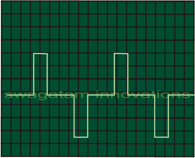
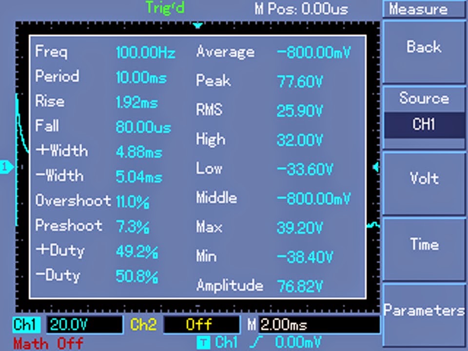
Waveform Images
The above design was tested and verified by Mr. Robin Peter one of the avid hobbyists and contributor to this blog, the following waveform images were recorded by him during the testing process.





Questions & Answers
Engineer,I thank God for the special knowledge given to you to design all these circuits.I appreciate your noble effort and talent.Please,I want you to help me with the information on how to wind the transformer.
1.3000 Watt
2.150 Amp
3.18V-0V-18V and 12V Center tapping (for Primary)
4. 600V-230V-0V(for Secondary side)
Please, I need the information about the size of the metal plate,Bubbin, wire gauge and the turns. I will grateful if you help me.
Thanks.
Hi Daniel, Thank you for your kind words.
designing a 3000 watt transformer is serious thing, and 600V high voltage can give dangerous shock, so be very careful with insulation.
First for core size you need big EI silicon steel stampings, like EI 180 size. Stack height should be around 10 cm so core area becomes roughly 60 sq cm. Take a bobbin matching this 60 sq cm center tongue size.
For primary side 18V-0V-18V you need around 24 turns total with center tap at 12th turn. For 12V tapping, tap it at 8th turn from center. Since current is huge like 150 amps, single thick wire will be impossible to bend by hand. So braid 4 or 5 parallel strands of 8 SWG copper wire together to wind it.
For secondary side 0V-230V-600V you need around 410 turns total. From 0 to 230V wind 157 turns using 12 SWG wire. Then from 230V tap to 600V continue winding another 253 turns using 16 SWG wire.
Put good quality Nomex or transformer paper insulation tape between every layer properly, otherwise spark will come in 600V side and burn the whole winding.
Hello Sir. this 1KV inverter is a great project. Just a pair of questions to you. In the diagram there’s a 12V buck converter. Would you mind sending me or telling me where can I find the diagram of that converter? What changes do I have to make in order to run this inverter with a 12V battery?
Thank you Pedro, glad you liked it.
You can use the following concept for building the buck converter stage:
https://www.homemade-circuits.com/adjustable-1-2v-to100v-dc-buck-converter-circuit-using-lm5164/
If 12V battery is used then transformer must be rated at 6-0-6/100 amps and battery must be rated at 12V 400 Ah
Hello, good evening, Mr. Swagatam. I would like to ask you a question about this inverter… Is it really a pure sine wave, just like the 220 VAC mains supply? Thank you very much in advance. 🤝
Good morning Carlos, no it is not pure sine wave but quite identical to it, and much better than modified sine wave, and should work nicely for most of the electronic equipment and loads…
Thanks alot sir please may I have the complete circuit diagram also I’ll be glad if I can get any information that will making me reaching you anytime I needed a help.. because there are so many components that I don’t know where I can buy them to avoid been fraud
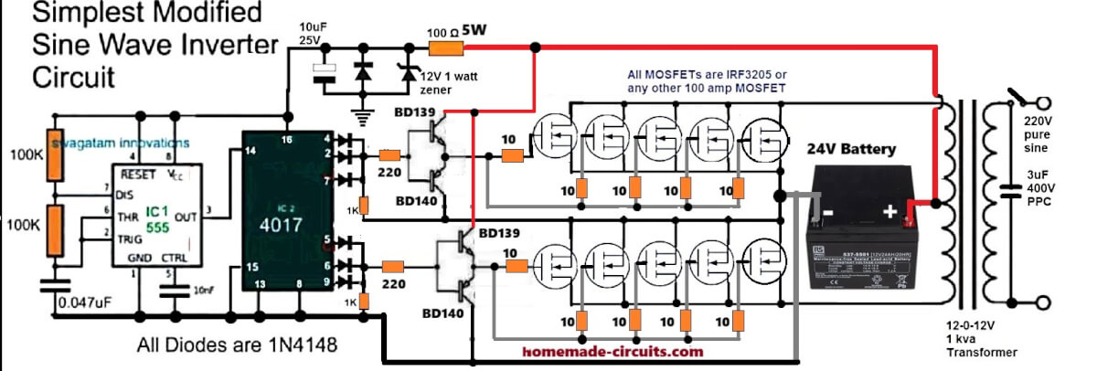
No problem Habeeb, here’s the full circuit diagram for you:
Good day sir and thanks you for your help, please can i use this circut diagram for printer used in cafe shop like printing in a4 paper and photocopying, secondly can i used 12v battery with this 1kva circuit diagram?
Hi Habeeb, yes you can use it for printer, but using 12V may require a huge battery and transformer.
12V would mean using a 12V 400Ah battery and a 9-0-9V/100 amp transformer.
Make sure to use separate gate resistors for each of the MOSFETs…
Good morning Boss.
1. Please kindly help with the images of:
– 0.047μf (ceramic or PPC)
– 3μf/400v (PPC)
2. Can I use 2.2μf/400v in place of the 3μf/400v in the circuit above?
Hi Kunle, these will look exactly like this capacitor:
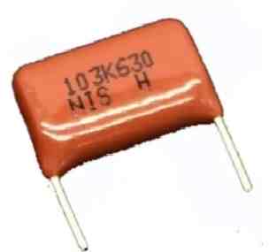
Yes, 2.2uF will do, but the filtering will be less effective than 3uF…
Sir, will this inverter still work fine with it’s 24v battery and 12-0-12 transformer without any side effects?
Hi Kunle, yes it will work safely with 24V and 12-0-12V transformer, you can do one modification to make it even safer, bring the 1k resistor directly across the gate and ground of the MOSFETs.
Good evening
I have just discovered your 1KW inverter, this circuit is complete with only 8 IRF 3205s.
1- I would like to start a 220V Mono 5.5CV motor which will drive a 220V 16KW alternator, to power my two OUTBAKK 48V inverters.
2-The Inverters are powered by 8 Rolls brand 6V 530AH batteries Battery 6V 530Ah C100 BX530
3-I have a 2×12 V /230V transformer of 1600W, less strong than in your diagram.
4-I would like to be autonomous without going through the national sector network.
5 – What power to start this engine.
Very nice presentation of your inverter.
Sincerely.
Gilou
Thanks, and glad you liked the first simple design….
You said you want to start 220V single phase 5.5 CV motor. That means about 4 kW mechanical power.
But you must know that when starting, motor needs very large surge current, normally about 4 to 7 times the normal running current.
So that means if motor is 4 kW then starting surge power can go up to 15 kW to 25 kW for few seconds.
You said your alternator is 220V 16 kW. So now, together with motor and alternator, total power becomes very big.
That is not simple. Very big power needed, especially at motor start time.
You told about 8 × 6V 530 Ah batteries, total 48V system. That is big Ah capacity.
But we must not think only about Ah, we must think about ability to give very high surge current.
That means several hundred amperes for few seconds during motor start.
You have 2×12V to 230V transformer of 1600W.
But that is too small, way too weak for this kind of job.
That transformer is only for small appliances, not for big inverters or big motors.
Yes it is possible to run fully autonomous system, not connected to national grid.
But then you must build very strong pure sinewave inverter circuit, big one, at least 20 kVA peak power,
And big battery bank, proper design, to supply enough current and Ah.
Also large MOSFETs or IGBTs must be used.
Battery wiring must be thick, very thick, to handle large surge safely.
My suggestion is:
Your system is very big.
Do not use small 1 kW inverter.
You need custom design for big load like motor plus alternator plus inverters.
If you want, I can help you design full strong system, no problem.
Good evening
First of all, thank you for your very detailed response.
I don’t want to drag myself into major expenses.
I will stay on my installation currently, that is to say start the motor with the 12V control at the output of my OUTBACK inverters towards the relay.
This relay supplies the 220V mains to the motor which drives the ‘Alternator to charge the batteries.
I will see the mains consumption for recharging the batteries.
Naturally if I don’t have enough sun or wind, my solar panels and the wind turbine.
I will consume more of the sector.
Thank you for your response, as many never respond.
Kind regards
Gilou
That sounds good! Thanks for your feedback and the updates. Wish you all the best!
Bonjour,
Je vous recontacte pour savoir s’il existe ou que vous avez publié sur un convertisseur de sortie d’un alternateur ou générateur 220V AC donc le signal est carré et non pure sinus.
Cela existe t-il.
Cordialement.
Gilou
Converting a sine wave from a generator into a square wave is actually not difficult.
We have to convert the 220V AC into 310V DC and then oscillate it into a square wave using an H-bridge circuit…very simple…
Thank you for your feedback.
But maybe I expressed myself badly.
It’s the opposite that I want to know.
(Convert a square signal produced by a 220V generator or alternator into a pure sine signal)
Sincerely.
Gilou
Thanks for the clarification, the google translate told me the opposite for your previous comment….
However, an alternator or generator will always produce a sine wave, never a square wave…???
for how long can it run using 24v?
can it run refrigerator and TV set at same time?
kindly help me with diagram that use mosfet 1010
To run a TV set and a refrigerator together, you might need to upgrade inverter design to 2000 watts minimum.
dear, friend I want making a Solar invertor 5 Kw 24 volt without battery. Please help me thanks,
Hello Abdul, with 24V, your solar panel will need to be rated at 5000/24 = 208 amps, which looks impracticable…
Hello! I know I’d already asked this circuit or subject 7 months ago but I revisited it today and I would to like ask again. The second circuit diagram that using sine generator circuit, is it pure sinewave circuit?
Yes, it is a pure sine wave inverter but the efficiency will be low due to high heat dissipation.
I’m interested buiding a power inverter and I like sinewave because of its nature that most elctronic devices it can be use. But on the other hand, I also read your modified sinewave 500 watts as well. Maybe I will just build latter first. In terms of effiecient, which is better the 1K sinewave or 500 watts modified?
Which 500 watt modified inverter are you referring to? Please provide the link of that article.
Can I use above H bridge ckt. for 24 v , 600Khz ?
I would recommend using the following circuit with the 4017 outputs, because it is much simpler.
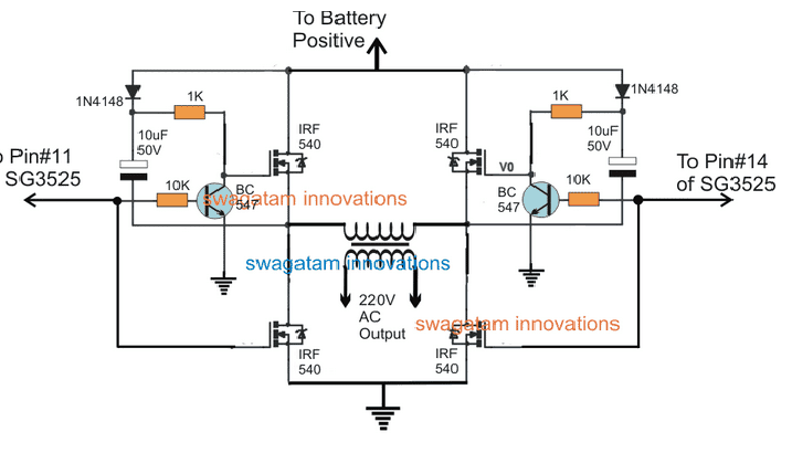
You can use 24V 600kHz with the above circuit.
Hey, I am new. In the Arduino based circuit diagram, I need only a 120 volt AC output. 220 is not required. What change can be done? Would really like to try this.
Hey Kerry, For 120V output you just have to use a transformer whose secondary winding is rated to produce 120V instead of 220V.
Thanks Swagatam. Do you know if there is a clearer drawing of the circuit somewhere?
No problem Kerry. I have an Arduino inverter article as given below. In this diagram you just have to replace the transformer with a 6-0-6V primary and 120V secondary winding. That’s all. If you this you will be able to get the required 120V from the inverter.
https://www.homemade-circuits.com/arduino-pure-sine-wave-inverter-circuit/
On the first schematic above. Is it modified sinewave or pure sinewave? cause on the diagram where in the transformer output there is “pure sinewave” written on it.
The first circuit will produce almost a pure sinewave AC once the 3uF output capacitor is connected.
Hello sir, i really appreciate the help you are rendering.
How can i use egs002 pure sine wave mosfet driver in the above circuit?
Hello Olusegun,
The EGS002 is itself a sine wave inverter module which can be configured with external mosfets for high power output. For the circuit diagram you can refer to the following article:
https://www.homemade-circuits.com/egs002-datasheet-circuit-diagram-explained/
Sir please. if I need any amount of power of my desire all I have to do is to keep increasing the BATTERY, the TRANSFORMER and RESISTOR Living the MOSFET the way it is ?
Yes that’s correct…but MOSFETs may also be required to be upgraded. However since the first design already has many high power mosfets connected in parallel, they won’t require an upgrade for 3000 watts.
Calculate Battery, Transformer, MOSFET in Inverter
With the diagram in this Article, it means it can take up to 3,000 watt without upgrading the recommended MOSFET already used in this Article… Is that correct?
I think you are referring to the IRF3205 msofets, yes that’s correct, if the mosfets are connected with large heatsinks and the battery voltage is around 48 V.
Sir please how can I increase the power to 3000w on the first diagram
Samuel, It can be done by using a 48 V 300 Ah battery, 24-0-24V 150 amp transformer. Change the 100 ohm 1 watt to 1K 2 watt
Thank you sir for answering my previous question Please can i use it to power my television and refrigerator.
Yes you can use it.
Sir please in that first article if I use 4 mosfet and 6v 50amp transformer with 12v 45ah can i get 1500watt
Hi John,
For getting 1500 watt a much bigger battery will be required. It should rated as follows:
1500 / 12 = 125 amps. 125 amps will be the discharge rate per hour. So if 5 hour back up is required, the battery will need to be 125 x 5 = 750 Ah
Can I use your circuit diagram to make same productions ?
How many mosfets will I add in each channel to get 2kva at 12v/200ah battery
You can add 5 nos of IRF3205 on each channel
Yes you can use them for production.
Hello Sir.
Good day,inverter will remain among the focus among your projects.i saw an Arnduino,5v dc to ac spwm board in an online retailer with 17 pins. I didnt know much about Arduino.My question is how can i inco-orperate it to an inverter circuit,,,that is pin connections..Is it good for me to use a 24v supply for the inverter and 5v for the Arduino board.
Another question is …these online cheap china inverters,are they good.Does their template match with their output.
Thank you so much.
Thank you Patrick,
You can feed the SPWM from the Arduino into the base of transistor drivers to drive the transformer with the SPWM.
Yes 24V is better than 12V since higher voltage means lower current which in turns helps to keep the transformer size smaller and generate lower amount of heat on the mosfets.
I have never used a Chinese inverter so I am not sure how good they are. You can confirm it only after a practical testing.
You can get more information regarding how to interface SPWM Arduino with transistors in the following link:
Arduino Pure Sine Wave Inverter Circuit with Full Program Code
Hello.
It’s a nice job! I like simple decisions of difficult task! I’m sorry, but I want to ask here you one stuff. Did you ever designed high power buck 220DC-120AC pure wave 60Hz? I’m working on this project for my home. I would like to get some fresh idea. If yes, let me know please. Thank you.
Hi, thank you! you can see the following article, it explains a non-isolated 220V to 12 V buck converter circuit
https://www.homemade-circuits.com/simple-220v-smps-buck-converter-circuit/
hello there, i wasw wondering as in the first section u staged 10 pairs of the bridge to get the 1000watts hence 1kva but in the lower figures where us showed “full 1 kva circuit” there were only 4 of them 200watts i can guess. is it on purpose to shorten the image size or is it actually just 4 of them?
Hello, if you use two 50 amp MOSFETs in parallel as shown in the last diagram, that can be sufficient to deliver 1000 watts of power at 24 V…therefore there’s actually no need of employing more than 2 mosfets per channel.
ah i get it. btw the MOSFETs that you have recommended don’t do more than 7A at 100watts. the datasheet by renesas (current distributors of the fet) any recommendation for the n and p channel mosfets that can do 50A?
Getting a 50 amp P channel mosfet looks difficult so better to go with 4 nos of IRF540, and IRF9540 each for achieving 1000 watts.
also those mosfets are obsolete now . especially 9540
part availability would not be that big of a problem as a lot of it is available at Digikey India. the only issue I am having is the schema in=mages are too blurry and low res.
right click the image and open it in a new tab…the image is quite big and the part numbers are clearly visible. You can look for 50 amp 100V p-channel n-channel mosfets in shops
Hi Mr Swagatam !
I read each one the questions people has sent to you and yours attentive answers. Congratulations on your exceptional patience and willingness to help! As a 72-yo retired technician (from valve time) I am taking the challenge of making an H bridge capable of sinusoidally supply 120Vrms @ 10A at 60Hz switchable to 120Vrms @ 10A at 1 to 4H ! over inductive load . Is it possible to achieve this using SG3525 or ,if not,could you suggest another way? To make things more difficult I must use single supply! Thanks in advance for your orientations .
Hi Mr. Oswaldo,
I am always happy to help and be attentive to dedicated readers like you! Thank you for stopping by and writing this question!
An SG3524 is actually a PWM IC which can be used for easily achieving constant outputs and over current protection features.
So if you want these features also in your inverter then SG3524 can be recommended, if not then the straightforward IC 4047 would be more suitable.
However, the main issues with an H-bridge is its rather complex working design, which calls for specialized driver H bridge ICs as I have explained below:
Simplest Full Bridge Inverter Circuit
The above links explains H bridge using Nchannel MOSFETs exclusively, which are supposed to be more efficient.
If a little lower efficiency is acceptable then an easier alternative can be tried using 2 P channel and 2 N channel MOSFETs, without involving complex driver ICs as given below:
Easy H-Bridge MOSFET Driver Module for Inverters and Motors
Hope this helps
Hi Mr Swagatam !
Since your answer I tried unsuccessfully to get sinusoidal shaped output using SG3525 ,then I saw a post looking for your guidance to build something similar to what I need .
“I have a 2012 & 2013 Prius, The Prius is unique in that it has a 200 VDC (nominal) high-voltage battery pack etc. etc ”
So I gave up on the SG3525 and set up the circuit with IRS2453 (took a long time to get then from China) exactly as shown in https://www.homemade-circuits.com/5kva-transformerless-inverter-circuit/. For the bridge 4 x IRGP4062D, RT 120K, CT 100K nf providing about 60Hz at IRS2453 pins 6/7. Frequency 5.5Khz, 50% dutty cicle at 741 pin 2 Vcc=50V.
I have been trying sleepless nights but no way to get sinusoidal output over the load for test(93R) even adding large amount of capacitors and / or increasing the inductance of the low-pass filter. Using 741 After 3 minutes low side IGBTs extremely hot (31,4Vrms@93R) .Replacing to LM383 , 27Vrms and everthing is cold ! . Sent diagram and scope photos to your email hopping you could help to find a solution .
Hi Mr. Oswaldo, you cannot build a complex inverter circuit by simply assembling the parts….you will have to understand each and every section of the design and then check them separately using an oscilloscope, and then finally integrate the stages to complete the project.
Before attempting the sinewave you must first successfully build the square wave version and then upgrade it to sine wave.
The following design will provide 100% sinewave you you build it step wise and correctly:
Bună dragul meu doresc să știu care este tensiunea de lucru în poarta tranzistorului Mosfet cît trebuie ca să lucreze 3v-5v -10v cevaloare este optimă casă nu se ardă tranzistorul am un montaj de invertor care se alimentează la tensiunea de 36v cam atît știu să explic mulțumesc .
The MOSFET gate voltage will keep varying according to the music level, from minimum to maximum supply voltage 60 V.
Since it is configured as a common drain amplifier, the gate source voltage will be always be between 7 and 10 V.
Sir, I am working on an H bridge sine wave inverter for 500W at 12V. I am able to convert the 12V DC battery to 12V AC at 50Hz doing open loop simulation. But when the load is connect the current is very low. How can I improve my power rating. Can you share reference material to design inverters with random power ratings at random voltages, like a generalised case.
Haizon, for 500 watt output, the current must be rated at 500 / 12 = 41 amps. Which means the battery must be rated at minimum 200 Ah capacity. So please simulate using a 12V 200 Ah battery
Simulated using 200Ah battery Sir
Still the current at the output is 0.6A at 12V.
Simulation results are often not accurate, instead if you build and test your set up practically then I think you can accomplish the results correctly…
Sir how can we fix it as 200Ah. Can you please explain how to choose 200Ah.
Manolis, yes you can use your mosfet amplifier for getting a pure sinewave AC output, by applying the input sine generator and 60V SMPS.
Sir, I have reead many article in electronic, and also from your site, and still yet am unable to start building circuit that are simple,
Pls sir how can I come over this challenges.
I will greatly appreciate your response sir.
Thanks in advance
It will take a lot of time and will require consistent reading and experimenting practically.
Hey swagatam ,pls I want to build auto battery charging cut off for my homemade inverter thanks in advance
How to wind the transformer for this inverter or which transformer can I use to make it
can you plz send me the clear circuit diagram of 1kv inverter
winding yourself is not required, you can buy it readymade by ordering a 0-9V / 50 amp / 220V transformer.
sir 50 amp or 5amp
divide 1000 by the battery voltage.
if your battery is 12v then 1000/12 = 84 amps, for 24V battery this will be 42 amps, for 48V battery this will be 21 amps.
the above are the current ranges for the transformer…the voltage of the transformer primary should be slightly lower than the battery voltage specs.
I’m much interested in learning electronics, can you help me EE
sure, if you have specific questions, you can ask them, I will try to answer…
Thanks you so much for your post and for sharing your knowledge.
I intend to build 3000 watt pure sine wave inverter with particular emphasis on pure sine wave aspect.
in my application i would like to have a circuit with a 230V output without any sine wave distraction.
Can you please give me some guide lines.
which of these drawings fits better, what changes will i have to make to have 3 kVA.
Thank so much for the help
Thanks, I think you should try the following concept which is more efficient than the above explained concept, since it works with SPWMs.:
https://www.homemade-circuits.com/1500-watt-pwm-sinewave-inverter-circuit/
thanks for your reply.
to better explain my application I intend make an AC power regeneration, meaning having the main 220V convert it to DC and then regenerate back to AC with low output impedance and proper 50Hz sine wave.
since I won’t need a battery maybe this project can be also transformerless?
if you could help me i would be very grateful
Then you won’t need a circuit? you can simply use two transformers, connect the low voltage sides with each other, and use one 220V side for feeding the mains input and the other 220V side to get the required low current 220V AC.
Hi. I just want to find out how I can calculate the Watt values of the 0.2R resistors in series of the sources of the mosfets in the sine wave inverter circuit. I am using 2 x 12 V batteries. So I’ll use a 24 transformer for primary, 220V secondary, but also 500VA, not 1kVa. This resistor Watt values are very important as the current flows through them,also causing a volt drop across it, and also to prevent thermal run away on the mosfets.
Can you please check my calculation in this regard
Va of transformer = 500VA
I through coil = 500VA/24V
= 20.833A
Now I thought that because I only want to work with the upper half of the wave form, I’ll divide that by 2, also because of duty cycle
So I saw that the current will be 10.416A
Now this resistors are in parallel, 2 of them with the same value, so to determine the current through one of the resistors I’ll have to divide by 2 again because it is the same in value. (Current divider)
So then I get a current of 5.208A
Now for this specific resistor (one of the 0,2R resistors), it is I*I*R
5.208*5.208*0.2
That gives me a value of 5.4W for each 0.2R resistor in the circuit.
Do you think this calculation done correctly
Thank you for you support in this regard
Hi, If you are not using two batteries then the average could be 10 amp, and the calculations appear to be correct.
Hello. Firstly, thank you. I need a minimum frequency of 4000 Hz in the part made with Arduino. I run this value via code. I get distorted signals at 4kHz on the oscilloscope on Proteus.
1-) What should I do in the code section to fix this?
2-) How many uF capacitors and how many ohms resistors should I use on the circuit, what else do I need?
Thank you again 🙂
From the wave forms,I don’t see a pure sine wave
The last circuit is a modified sine wave…the circuit with two op amp input will produce pure sine wave.