XL6009 is a DC-DC switching regulator IC, and we use it where lower voltage DC has to be lifted higher, or sometimes changed other ways, boost, buck-boost, flyback, even inverting, all that is possible depending how outside parts are connected.
Why XL6009 is More Efficient Than Linear Regulators
It is not like old regulator types which waste more power because here inside it already has current-mode control and one internal MOSFET and that MOSFET switches at fixed 400 kHz. So now outside circuit stays small but still output power comes quite efficiently.
Input Voltage and Current Handling Capability
Input side can take 5V up to 32V and internally switching current can reach 4A. However practical current always depends on PCB copper, inductor quality, diode quality, heat, all these decide what really comes outside.
Main Features of XL6009
Main things people notice first are wide input range, adjustable output, fixed 400 kHz switching, internal 4A switch, thermal shutdown, current limiting, soft start, and EN pin which is TTL friendly.
So yep because of that it fits battery jobs, automotive lines, solar side, portable units, many small power circuits.
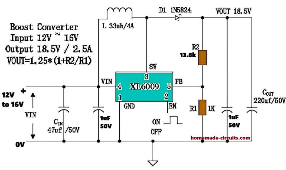
Circuit Diagram
Package Type and Pin Count
This IC comes in TO-263-5L package, five pins only, so pin side is simple.
Pin 1: Ground Pin
Pin 1 is GND, that is full ground line.
Pin 2: Enable Pin Function
Pin 2 is EN, enable pin, which means if logic goes high then converter runs, if logic goes low then it stops, and if left open then internally it stays ON.
Pin 3: Switching Pin Function
Pin 3 is SW, switching pin, where inductor sits, and this pin carries fast pulses all the time while working.
Pin 4: Input Supply Pin
Pin 4 is VIN, input supply pin, where 5V to 32V enters, and here one low ESR capacitor must sit close, otherwise noise can rise.
Pin 5: Feedback Pin and Output Adjustment
Pin 5 is FB, feedback pin, which senses output through resistor divider and keeps FB at 1.25V.
Output Voltage Formula
So output follows:
Vout = 1.25 * (1 + R1 / R2)
Where R1 is upper resistor and R2 lower resistor.
How the XL6009 Circuit Works
Inside the IC, there's a MOSFET which switches very fast at 400 kHz.
During ON time current enters inductor and magnetic energy builds there, then when MOSFET turns OFF that stored energy comes out through diode and charges output capacitor.
Therefore output voltage rises above input, and we get a boosted voltage output.
Advantage of High Switching Frequency
Since switching speed is high then smaller inductors and capacitors work fine, which older low frequency designs could not do easily.
Basic Boost Converter External Components
A basic boost setup needs one inductor, one Schottky diode, two capacitors, two feedback resistors.
Typical Component Values
Typical values stay like this, inductor 47uH to 68uH, diode fast Schottky 5A type, input capacitor 220uF, output capacitor 220uF, then divider resistors by required output.
Importance of Correct Inductor Selection
Inductor must be low resistance and should not saturate early, because that is where many failures begin.
Example for Setting 12V Output
If 12V output is wanted, and if R2 = 3.3k, then R1 comes near 28k, so 27k or 28k both are used practically.
Inductor Current Rating Requirement
Inductor current rating must always stay above peak input current because if 5V is boosted to 12V at 2A, then input current can go up above 5A for moments, so then inductor should not be below 6A rating.
Recommended Diodes for XL6009
For diode, only fast Schottky should be used, like SS54, MBR540, or SR560 because slow rectifiers heat and drop efficiency badly.
Practical Output Current at Different Boost Ratios
Although datasheet says 4A switching current, practical output changes with boost ratio, so 5V to 12V gives near 2A practical, 12V to 24V near 1.2A, and 24V to 48V mostly below 0.8A.
Limitations of Cheap XL6009 Modules
Cheap modules often claim more, but weak inductors and thin PCB copper then limit real current, and hmm many users see overheating when driven hard.
EN Pin Logic Levels
EN pin can also be used for remote control, below 0.8V means OFF, above 1.4V means ON and if microcontroller is used then transistor interface is safer when VIN stays high.
Common Applications of XL6009
This IC fits battery boost work, solar booster stages, automotive voltage lifting, LED driver side, inverter pre-regulator, negative voltage making, and even SEPIC forms.
Using XL6009 for Negative Output
It can also make negative output, for example +12V input becoming -12V output but then diode polarity changes, capacitor polarity changes, and ground reference also shifts.
PCB Layout Guidelines
PCB layout matters a lot. Keep SW copper short, diode close to IC, input capacitor near VIN, ground track thick, and feedback line away from switching path because if layout becomes bad then ripple and noise come quickly.
Thermal Management Requirement
At higher load, copper area under the IC should be large because TO-263 cools mainly through PCB copper and if that heat cannot spread then thermal shutdown starts.
Why XL6009 is Popular
Why it is popular is simple, circuit stays easy, outside parts are few, voltage range is wide, modules are cheap and current-mode control stays stable. so even now though newer synchronous types exist, XL6009 still remains very practical for daily power conversion work.


