An efficient solid state single pole double throw or SPDT switch can be built using triacs for replacing a mechanical SPDT.
In this post I have explained a simple solid state triac SPDT relay circuit, using an optocoupler and a couple of triacs, which can be used as an effective replacement for mechanical relays. The idea was requested by "Cypherbuster".
Introduction
In one of the other posts I have explained how to make an DPDT SSR using mosfets, however this design could be used only for high current DC loads, and not with AC loads at the mains level.
In this article we will see how a simple mains operated solid-state relay can be made using triacs and an optocoupler.
The working of any relay is specifically intended to operate two different high power loads individually and alternately with the help of an external isolated low power trigger.
In a conventional mechanical type of rely this is done by toggling the loads across its N/O and N/C contacts in response to the activation applied across its coil.
However mechanical relays have their own drawbacks such as higher degree of wear and tear, lower life, generation of RF disturbance due to sparks across the contacts, and the most vital being the delayed switching response which could be crucial in systems like UPS.
Circuit Operation
In our triac SPDT relay circuit the same function is executed through the switching of two triacs via two BJT stages and an isolating optocoupler which ensures that the changeover operation for this relay has no drawbacks as mentioned above.
Referring to the diagram, the left side triac represents the N/O contact while the right side triac operates like the N/C contact.
Circuit Diagram
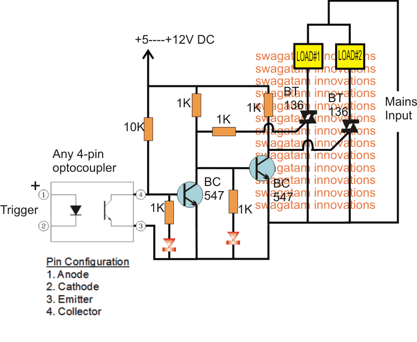
While the optocoupler is in the non-triggered mode, the BC547 directly associated with the opto goes into the triggered mode, which keeps the second BC547 switched OFF. This situation enables the right side triac to remain switched ON, and the other triac is held switched OFF.
In this condition any load connected with the right triac becomes operational and stays switched ON.
Now as soon as a trigger is applied to the opto coupler, it switches ON, and in turn switches OFF the connected BC547.
This situation switches ON the second BC547 and consequently the right side triac is switched OFF, ensuring that the left side triac is now switched ON.
The above condition immediately toggles the second load ON and switches OFF the earlier load, effectively fulfilling the required alternate switching of the load with the help of an isolated external DC trigger.
The two LED connected with the bases of the two BJTs indicate which load is in the activated state at any moment while the triac SPDT relay circuit is being operated.
Adding an attached power supply and Delay Effect
The above design could be further enhanced and made fully independent of an external DC power source by upgrading it with its own transformerless power supply, as shown below:
You will find the following changes in this upgraded diagram:
Addition of a 1K at the base of the right BC547 to ensure correct triggering of the left side triac
Addition of R/C network across the gates of the triacs to ensure that the two triacs are never ON together at any given instance or during the changeover periods. The diodes can be 1N4148, resistors can be 22K or 33K, and the capacitors can be around 100uF/25V.
There's one more thing that seems to be missing in the diagram, and it is a limiting resistor (approximately 22 ohms) between the 12V zener diodes and the 0.33uF capacitor, this may be important to safeguard the zener diode from sudden in rush surge through the capacitor during power switch ON.
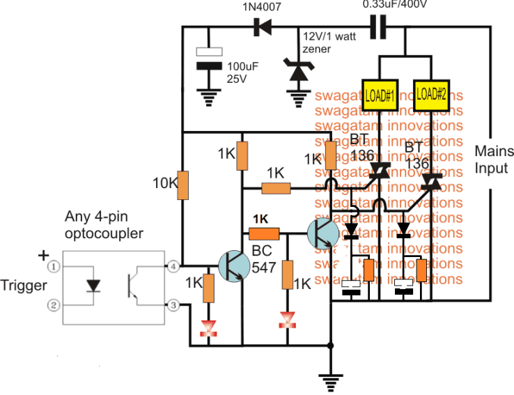
Warning: The circuit shown above is not isolated from the mains AC input supply and therefore is extremely dangerous to touch in the switched ON condition.


Questions & Answers
Thanks a Ton!
Another thought: A relay does not require a continuous power supply, i.e, even under no power conditions, there's a connected terminal and an open terminal.
Would it be possible to do away with the external 5-12 Volt and make this an exact Solid State version of a relay?
I am glad you liked it…please check out the last diagram I have updated it as per your suggestion.
It is my pleasure Devendra ji. thank you and God bless you!
Sir i dont find transistor BC517 sir can i use BC547 replace of that Transistor ??
you can use two BC547 and connect them in Darlington form for getting the equivalent of BC517
yes that's possible.
Hello Swagatam,
I have sent the modified diagram on mail, as you had suggested. Please have a look and let me know your valuable feedback.
Thanks,
Puneet
Hello Puneet, I have replied it.
Hi Swagatam,
One more query in your mail, please suggest.
Thank you
answered!!
Brother,
Can you provide circuit for three phase Solid State Contactor.
Thanks.
sure bro, I’ll do it soon using heavy duty triacs.
Do you need a capacitor delay of some sort so both NO & NC aren’t on at the same time? Even, ever so slight?
Great Circuit — !
Thanks Lane for pointing it out, I have updated the design with the delay feature at the bottom of the article, you can check it out.
Great Circuit. Does this work with 230v ac?
Yes, the last circuit can be used with 220V AC
Thank you very much for your quick reply Swagatam.
Great Site. Have a great day.
You are welcome Craig!
Hi, can I use triac for control in between AC Transformer 440v output and diode bridge ? load is inductive
Yes, you can use it…
Thanks for your quick reply, Based from your circuit without outside bat source , I analyze it ( Triac gate can be trigger only by positve polarity ) and looking on the cct we can use only the positive cycle to trigger the Triac. It means the supply to the load will be intermittent supply. Do I am right ?
Without the +5 to +12V source the circuit will fail to function. No, the load working will not be intermittent because the both triacs MT1 is connected to the circuit’s common ground…
Re: Triac is 2 SCR parallel. I need a high voltage Triac but its expensive in the market. I have several stock of High voltage SCR. Can I connect it in parallel and connect together the two gate to function as a Triac ? any disadvantage of doing this connection ?
No, practically that’s not possible and may malfunction, you must use only a triac…
Many thanks for your quick reply
Can two triacs be connected in parallel to double the current consumption? What is the connection diagram?
Sure, you can try the following method:
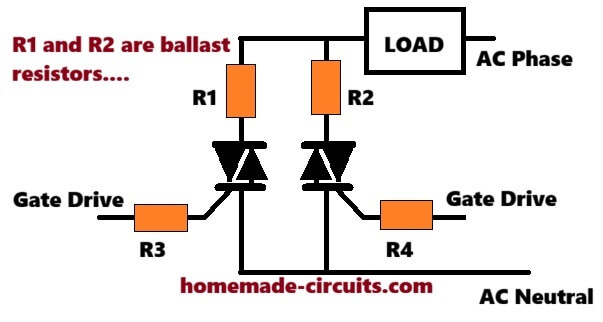
As a rule of thumb for safety, you should always double this power calculation so the component runs reliably without burning out. For a 15-watt requirement, you should use a ceramic wirewound or aluminum-housed resistor rated for at least 25 Watts or 30 Watts.
If you want a quick shortcut without doing the math, using a ballast resistor between 0.1 Ohms and 0.22 Ohms rated for 10W to 25W works as the sweet spot for most common setups running between 10A and 30A. Anything lower than 0.1 Ohms won’t balance the current effectively, and anything higher will just waste too much power as heat.