
In this article I have explained a set up for testing MOVs which are special devices specified for absorbing instantaneous high surge currents that may accidentally occur in our mains electrical lines. The idea was requested by Mr. Kevin
Technical Specifications
I'm Kevin Montañez, a university Electrical Engineering student here in Cebu, Philippines. As I told you before, I will get back to you if I have more questions. 🙂
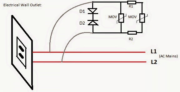
I am hoping you'll entertain my query again. Attached is the surge protection circuit we have decided for our group research/thesis. This is just one part of our project which is to have a built-in sure protection for wall outlets using 2 diodes with cathodes connected to each other and MOVs.
Although you have recommended before to use NTC thermistor instead of fuse or diodes, but I am concerned that it will cost much than the diodes. These are my questions:
1. Here in the Philippines, it is not practiced to have grounding in most residential buildings unless residential buildings for rich people of course they have.
Many buildings here are connected line-to-line instead of line-to-ground as practiced abroad. One of the characteristics of MOV is to absorbed excess voltage, where its resistance will drop, eventually current will flow to it and will be absorb.
The absorbed current will be dissipated to the grounding rod. My question is, how to dissipate the current in a line-to-line connection?
I am asking this so that by the time we will defend for our thesis, we could test it in front of the panel, sadly the school is not line-to-ground connected, and outlets don't have grounding connection.
2. How to test the varistor (MOV) to know if it really works? If it really absorb the surge voltage/current? Say for example, if a motor will be connected in our proposed outlet, it will require a large starting current. How to check if the varistor really absorbed it? What instruments do we need to conduct such testing?
3. How to test as well the 2 diodes with cathodes connected to each other?
4. I'm curious as well since you recommended before to use NTC thermistor, what usual rating would it be for the thermistor for this kind of application? How to test if it work?
I'm praying that you will read and respond to this soonest. I'll attach my email address if you prefer to respond there.
You really are a big help for our thesis and your blog and ideas are a great help as well especially for us students. Please do help us pass this subject.
Thank you very much for sharing your knowledge in Electrical Engineering! Gob bless you more!!!
Best regards,Kevin Montañez
Solving the Circuit Query
An MOV is required to be connected across LINE and NEUTRAL and not LINE and GROUND, so ground may not be required for MOVs, basically it simply needs to be connected across the load mains input terminals.
An MOV is designed to protect against instantaneous high voltage surges that may last for not more than a few nano seconds....for example if there's an instantaneous voltage spike of say 600 V for 3 nano seconds, the MOV will happily neutralize it by short circuiting it across the connected terminals.
However if this spike sustains even for a second it could cause the MOV to get destroyed and catch fire.
To demonstrate how to test an MOV you would need a 600 V AC source derived by stepping up the domestic 220 V through an auto transformer, and make the circuit set up as shown in the diagram.
Circuit Setup

The figure shows a bridge network which rectifies the 600 V AC to 700 V DC and this DC is then fired across the MOV circuit carrying a vulnerable 220 V, 10 watt lamp.
This is done through a 2uF/1KV capacitor in order to protect the MOV as it's not designed to handle sustained high surges.
Normally the connected lamp would instantly get burnt when subjected to this massive 700 V, but the experiment will hopefully show how the massive voltage is successfully absorbed and neutralized by the MOV saving the bulb's life.
The diode set up is not recommended, because TVS diodes can act like short circuit if they happen to get destroyed, this would mean the wires catching fire or the fuses blowing of.
An NTC can be selected as per its maximum voltage rating specs, this voltage rating will determine how much instantaneous high voltage the device is rated to restrict.
A Very Simple MOV Tester Circuit

The above design appears to be a simple and an effective MOV tester circuit which can be quickly used to verify the clamping voltage of any MOV. It can be also used to verify whether the MOV is actually good or a bad one.
The idea is simple, when we press the push button, the mains AC is passed through the 105 (1uF) capacitor and applied across the MOV.
If the MOV is working good, it will instantly ground the excess voltage and not allow the input voltage to rise above the specified clamping voltage of the device.
Thus, the maximum voltage will not be allowed to go past the clamping voltage of the MOV, and this cut-off voltage information will be delivered through the 1N4007 and stored inside the 100uF capacitor.
Since a voltmeter is connected across this 100uF capacitor, the meter will quickly provide you the voltage reading at which the MOV restricted the input mains voltage level.
If the voltmeter reading matches the clamping specification of the MOV that would indicate the MOV is good, any other results might indicate towards a faulty MOV.