A tap water heater circuit can be simply built by attaching an iron tube on the mouth of the tap or the faucet, and allow the iron pipe to pass through an induction heater coil. The induction heater will heat up the iron pipe and hence water passing through the the pipe will also heat up and provide a warm water for the user from the other end of the pipe.
Materials Needed
To build this project you will need the following basic materials:
A ready made induction heater circuit that can be powered from a 12V 10 amp SMPS DC power supply.
An appropriately fabricated metal pipe with Bakelite holder at one end which can be clamped to the tap mouth.
An appropriately dimensioned Bakelite box for enclosing the induction heater, the induction coil, and the metal pipe.
The Set Up
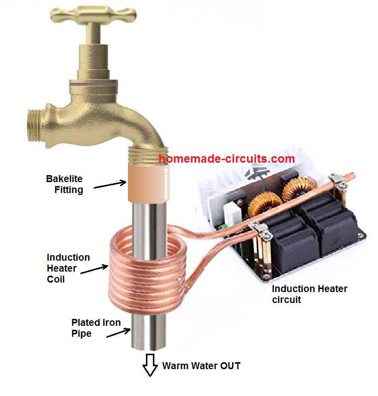
The complete set up for the induction tap water heater circuit can be witnessed in the following set up diagram:
In this set up we can see a plated iron pipe or a galvnized iron pipe is clamped to the mouth of the tap via a bakelite adapter cap. The bakelite cap ensures that the heat from the iron is not able to disperse to the tap metal, and remains instact within the iron pipe.
The iron pipe can be seen encircled by the induction heater coil, or in other words the iron pipe is allowed to pass through the induction heater coil.
The metal pipe diameter must be selected to ensure that the amount of water passing through it is not too large, and the water is able to get warm enough while passing through the pipe. The water coming out from the pipe must be at least 35 degrees Celsius warm.
How to Enclose the Whole Set up
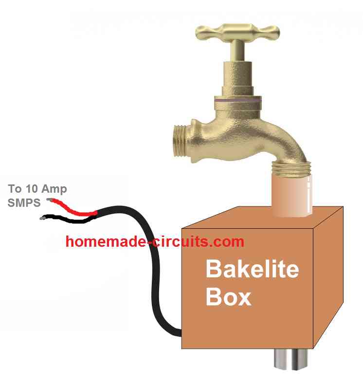
The above explained induction tap water heater circuit set up will need an appropriate enclosure which must be light, sturdy, water proof, heat proof, and could be attached to the tap system along with the iron pipe.
An example format of the enclosure can be seen in the following image.
The enclosure should have ample ventilation from the bottom side, so that the parts of the induction heater can dissipate the heat comfortably without getting too warm.
The power to the induction heater circuit enclosed inside must be supplied from an external SMPS unit, which may be rated at 12 V 10 amps.
Using the SMPS unit externally provides the user with an advantage of using the SMPS for some other desired purpose, when the heater is not being used.
Cheaper than Commercial Water Heater
If you compare the above induction based tap water heater circuit with commercially available geysers and water heaters you will find that the above set up is much cheaper and cost effective than the commercial units.
The complete set up can be built in less than $20, which is 50% less compared to the commercial units.
Also, the electricity consumption can be 50% less for the above explained concept, compared to the commercial heater units, which depend on heater coils rather than induction heating system.
Moreover, you get a free SMPS device which you can use for lighting LEDs, driving a power amplifier or a subwoofer amplifier, a benefit you can never get with the commercial heater units.


Questions & Answers
Iron or other metal makes very little difference. It is largely the electrical conductivity that an induction heater uses.
It has to be iron, otherwise induction heating cannot take place. The core has to be magnetic otherwise induction cannot happen.
Dear Swagatam,
Can I have more details of the induction coil. Where can I purchase it in India. Soecifications of the induction coil etc.
Thanks
Dear Ashok, you can try any 300 watt ZVS induction heater which may be available in any electronic retailer or online stores like amazon, bangood, robu etc.
Amazing idea!i can only say wow!.i am not a technical guye but,always facinated and intressted in the genious oft inventors Like you are.
the only thing i am afraid of is that like always,big companies don,t like it.
Thank you for your useful suggestions and glad you liked the project.
Dear Swagatam,
I think I have written a couple of times regarding this very type of thing. I haven’t seen a reply to them. I was thinking that using the 60hz house current around a pipe would work. I have bought the 12 v induction heater circuit and used it around a pvc pipe with a stainless steel scrubbie in the pipe. It did heat the water ok. What I would like to know is how many turns of copper wire I should use that would give the same effect with house current or maybe I’m just not understanding how an induction heater works.
Thank you,
John
Dear John, sorry i don’t remember where you discussed regarding the above concept, if possible please provide the article link where you have mentioned about this project.
Presently I do not have a 220 V or 120V directly operated induction heater circuit, all the designs that I have are 12V or 24V rated.
The turns of the work coil will depend on the resonance calculations of the design, the number of turns should match the calculated capacitance value for getting peak resonance, so basically it’s the inductance of the coil that becomes crucial.
Thank you, Swagatam. I guess I did not mention that concept directly when I wrote before. I was trying to figure out in my original post to you what the number of turns of what gauge wire would not burn up when connected the 120v household current. I had thought that if I could build the coil then I could figure out the capacitance value that would work best with that setup. So, I was still in the thinking phase of what is possible (Electricity is very hard for me to wrap my head around.) It is my thought that if I had a coil that would not burn up using house current (I am being safe) and not trip a breaker then I could experiment with the core size. The reason I thought the scrubby would work is because the water will flow through it and because of the fine wire it is made of would be able to heat the water more uniformly. I did, as I said before, get warm/hot water with a coil around a pvc pipe that had a stainless steel scrubby in it using the 12v induction heater circuit. I didn’t feel comfortable using that circuit because the circuit I had bought could only be used intermittently and what I wanted to build would to be able to keep running as long as I wanted (such as heating an in-floor water heating coil). I had also thought that the parts would be simple and inexpensive. I have regular utility power and if I could use electricity that already had a 60 Hz cycle for induction heating, it would be something I could work with. A method like that would not have to generate a lot of heat quickly. I know the higher frequencies are more efficient to get high heat but for me at this point it’s more than I can grasp how to build one.
Hi John, I think the concept that you are referring to may be feasible. We can use an appropriately number of turns over an iron pipe and try passing a high frequency 220 V or 120 V DC through it. Due to eddy current generation the iron pipe then would heat up fulfilling the objective of the experiment.
A similar type of concept can be seen in the following article:
Small Induction Heater for School Project
Thank you for your reply. Isn’t a dc frequency the same as an ac frequency? Anyways, as a general concept, what would the ball park idea be for the gauge of wire and the number of turns required so the coils wouldn’t get too hot. I know there are the small 120 volt ac to 5 volt dc wall warts and they use pretty fine wire. Would that be along the line of the gauge wire and the number of turns that would be needed to be safe? By the way, I always check the box below for an email notice that you have replied but haven’t seen an email yet when a post is made in reply. Am I not doing something right for that notice?
John
DC frequency will not change polarity, but AC frequency will alternately change polarity.
The wire gauge can be an 18 SWG, and the number of turns can be 100 turns minimum, which must wrapped around an iron tube and applied with a frequency of around 2kHz to 10 kHz
The emailing is a automated process done by the website, not sure what may be the problem, I am not an expert in these matters, will need to check it.
Dear Swagatam:
I looked at a wire gauge converter chart of mm to awg and it appears that 16 gauge would be able to carry as much as 10 amps. If I follow what you have in the School Project I could start with 50 turns. Then I could reduce the voltage by adding some resistance in the form of a light bulb or heating element. I could then safely check the results, increase the voltage or number of turns in the wire maybe. I think this is the basic idea that I could use to experiment and by trial and error find something that might work for me. Do you see a problem with this line of thinking?
Thank you,
John
Hello John, the procedure that you have mentioned is absolutely correct, however along with the voltage, it is the frequency that also matters. The frequency actually decides the number of turns that can be used. So along with the voltage you may also have to consider the frequency for fixing the number of turns.
Thank you, Swagatam. I really appreciate your responses and knowledge about this. I will give it a try, experiment with it and let you know how it works.
You are most welcome, John.
Hello John,
Were you able to give your idea a try? Curious what the results of your experiment were?
I need 1 tap water induction pcb what will the cost, roananth@gmail.com
Sorry Ananth, we do not sell electronic products from this website!
Yo quisiera fabricar uno para la ducha… ¿cual me recomiendan?
You can try the concept explained in the above article. There’s only one circuit concept explained above.
My brother is an engineer
I Watch all your respected engineering activity ; And your living conscience
And love to help others.. I respect you with all my heart and I wish you were my brother.
Egyptian radio officer
Naguib sawy
Thank you Naguib, I appreciate your thoughts, and I wish you all the best
You have 1full set with smps, total cost ?
Rs.1200/-
I need one full set with smps, message me in detail with your account gpay details for amt transfer.
by next month 1st week i will send you the amount by the mean time mail me all the details to roananth@gmail.com, 9740078871.
Send me your contact number also.
Best Regards
Ananth
Sorry Ananth, I won’t be able to build the unit for you due to work load and lack of time. If you need any other help please let me know.
Atleast can you send my the backlite fitting pipe tube remaining i will see.
If so send me the cost of it, i can gpay you. by Aug 1st week.
roananth@gmail.com
9740078871
Ananth
Hi, I have only designed the circuit, I do not have the materials with me. The bakelite box is made-to-order type, it is not available ready made from the market.
You will have to ask a bakelite dealer to build the box for you.
OR If you have no time you can send me the pcb and spare parts also, i will assemble it my self.
You cam easily purchase the 1000 watt induction heater from Amazon . com
I want to build a water heating system that will heat 1000 gal. per min. to a differential of 30 degrees C. I realize I will need a 600 Kw. generator to produce the power to to achieve that much heat in the water. Is this possible with an Induction geyer heating system or what do you advise. Archie
It can be achieved through induction heating, but the required setup will be quite huge.
I under stand that this is not a small project I just want to know if this project will work 100%. I see no reason if I supply enough heat to the heating area and the heating area is big enough to transfer the heat it should work unless it some how interfered with the electrical circuit.
The concept will work 100% if it is built as explained in the article or with some other more efficient technique. The induction heater power must be also selected appropriately depending on how much water from the tap is released per second.
thanks for the feed back. If you or any one else out there knows how to build this heater I would be very interested in talking to you. Archie
If I find someone who is willing to do it, I will let you know.
The water that I want to heat is a continua’s flow. I am hooking up to a larger pipe with water flowing under pressure, [they call this slipstreaming] with a ten inch stainless steel 3/16 side wall pipe. This pipe will be approximately 8ft. long it will hook up to the heating area. Lets say the heating area is a 20ft stainless steel 3/16 side wall by 4ft. diameter vessel with stainless steel auger type center coil welded all the way around for heat transfer. This auger will run the full length of the heating area. The flow and desired heat transfer will be the same. This water will then be pumped back into the line under pressure. The water does not stop it’s a continuous flow that just slows down in the heating area. Does this still work? I’m trying to make it more efficient for heat transfer and smaller generator. Archie
Yes, the water just needs to run slowly while passing through the heating col, this will ensure that the water is able to heat up properly while passing through the heating coil.
However, how much the water gets heated will ultimately depend on the power output of the induction heater.
If I used a pipe with fliting welded to the inside to make the water swirl this would probably be a better heat conductor.
Yes, that sounds a very good idea. However this has to be maintained within the internal diameter of the induction coil
sorry for repeating myself I had another issue on my mind
Sure, please feel free to ask.
Will one of these heaters keep heating 24/7 under full load if you keep the water cool for the circulating coil lines. I was thinking we could just build a small copper cooling coil in the main water line to control the temperature of those lines.
Yes that may be possible. If the water does not heat correctly then the power of the induction circuit will need to be increased appropriately.
Archie again; Lets approach heating water with electromagnets. If we set up electromagnets out side this 10 inch water line wrapped with copper tubing to conduct electricity and used the water flow in the 10 inch pipe to spin the electromagnets. We would then connect the copper tubing up to the flowing water in the 10 inch pipe to transport the hot water into the 10 inch pipe. Hope this is not to confusing Archie.
That would make the setup greatly complex, which is not required according to me.
Hi, thank you.
I very much woud like a heater to warm shower water to maybe 50 or 60°C, not even 9l/min which is my gas unit now never on full.
Ac or Dc…? Inverter or battery? 24vdc or 240vac?
Regards
Hi, the induction heater shown in the above article usually works with a 12V 20 amps or a 24V 10 amp DC power supply.
This could also be used to heat the water for a central heating radiator. Either a whole system or just a standalone radiator, set with a water temperature thermostat to keep the water at the ideal temperature. This would be a very economical way to heat your room or home.
Thank you for your useful suggestion!! I completely agree with you.
Great and respectful ideas. I have an idea and we need to cooperate in it to get out for everyone well and effectively, which is to convert the steam tank to the average steam iron about 3 liters of water or a little less to use the house or small projects so that we dispense with the traditional heater and replace it with a heated heater.I know that the project is not simple, but I also know that it is not very difficult, what do you think, dear engineer
Yes that’s possible using an induction heater, rated appropriately…
I’m looking at this to maintain the 180 degree temperature in my hydronic boiler return line that is 1 1/4″ copper pipe attached to the boiler via an iron pipe inlet.
Could this simple circuit be used and temperature controlled to do that? I know there are plate exchangers that can be used to do this, but I have solar panels that can provide 12v DC via an EcoFlow Pro 3 battery system to this induction circuit.
Yes, it can be customized for your specific application, by appropriately upgrading the work coil dimension and the input current capacity.