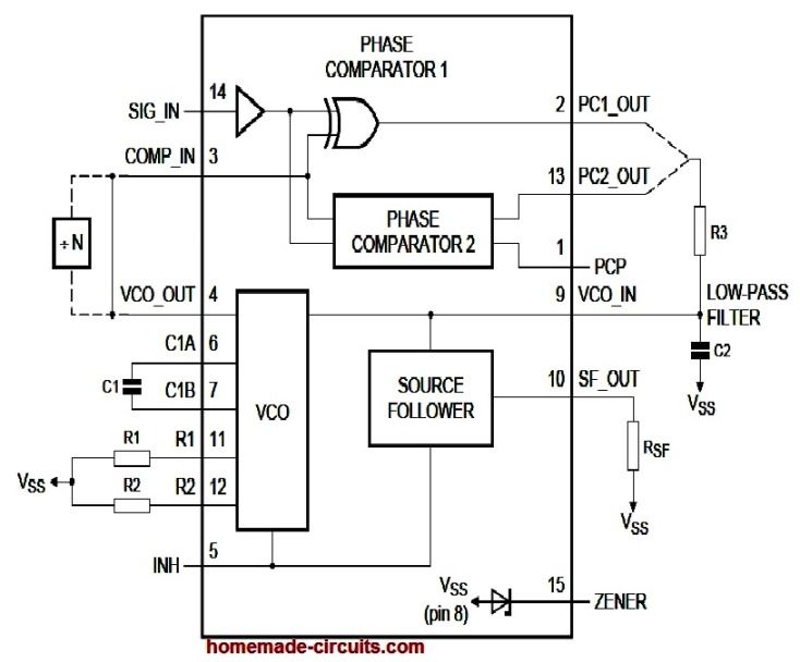
IC 4046 is a Phase-Locked Loop (PLL) chip that consists of various functional blocks such as a voltage-controlled oscillator (VCO), phase detector (PD), phase comparator (PC), charge pump (CP), and other circuitry. Here is the datasheet for IC 4046: General Information: Electrical Characteristics: Features: Pin Configuration: The pinout configuration of the IC 4046 can be […]
Pinout
IC 4063 Datasheet, Pinout Working, Applications
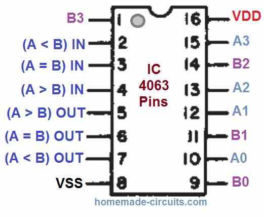
The IC 4063 is a CMOS-based 4-bit magnitude comparator IC that can compare two 4-bit binary or BCD numbers and determine which one is greater than or equal to the other. It operates on a supply voltage range of 3V to 18V and is compatible with TTL logic levels. Features: Some of the key features […]
IC 4040 Datasheet, Pinout, Application
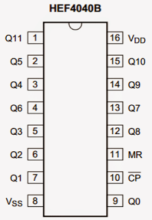
The IC 4040 is technically a 12-stage binary ripple counter chip, in simple words a device which will produce a calculated delayed frequency output in response to every pulse applied at its clock input. This delay is incremented at the rate of 2n where n is the pinout order in the sequence of its outputs. […]
L293 Quad Half-H Driver IC Pinout, Datasheet, Application Circuit
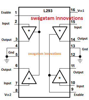
In this post we investigate the technical specifications and pinout details of the IC L293 which is a versatile quad half-H driver IC, and can be used for implementing many interesting motor driver based circuit applications, such as for operating motors, solenoids and other inductive loads (4 units separately or in pairs through push-pull mode). How […]
IC 4013 Datasheet, Pinout Details
IC 4013 is a CMOS-based dual D-type flip-flop integrated circuit. It is widely used in digital circuits for applications such as counters, shift registers, and control circuits. Below is the detailed datasheet for IC 4013. Pin Configuration: IC 4013 has a total of 14 pins. The pin configuration is as follows: Pin Name Pin # […]
IC 4016 Datasheet, Pinout Function
IC 4016 is a CMOS-based quad bilateral switch integrated circuit (IC). It may be used for a variety of purposes, including waveform generation, voltage-controlled oscillator, switching of audio and video signals, and controlling analogue and digital signals (VCO). A thorough datasheet for the IC 4016 is I have explained below: Electrical Characteristics: Pin Configuration: The […]