• Skip to main content
  • Skip to primary sidebar

Homemade Circuit Projects

Need circuit help? Post them in the comments! I've answered over 50,000!

Blog | Categories | About | Contact | Calculators-online
You are here: Home / Solar Controller Circuits / Solar Boost Charger Circuit with LED Driver Dimmer

Solar Boost Charger Circuit with LED Driver Dimmer

Last Updated on January 8, 2024 by Swagatam 6 Comments

In this article I have explained a simple solar boost charger with LED driver circuit which also includes a single push dimmable feature. The idea was requested by Mr. Ashutosh.

Table of Contents
  • Technical Specifications
  • The Design

Technical Specifications

Hi swagatam,

Myself Ashutosh. I m very new to ur website, n i ll say u r superb, u r doing one of the best thing by helping hobbyists. Thank you very much. I want an LED driver cum charger circuit for our project. i know u already have thousands of request pending and at the same time u might be working on different circuits, even though i want to ask for it, my circuit details are as below-

1. It's an LED lamp
2. Having 3volt (0.5watt) of solar panel for charging the battery.
3. Have to charge 3.6 volt battery from the solar panel (for this may be some boost ic is required ).
4. Regarding switching---> have one switch---> when all the connection are there the LED should be in off mode---> after 1st press it should glow in full brightness i mean 100% duty cycle----> 2nd time when i press 2nd time the switch the LEDs brightness should decreased by 40-50%---> when i press the switch 3rd time the LED should get more dimmed(say the brightness should decreased by 70-80%)----> and when i press the switch 4th time the LED should get off.
5. Circuit should be very compact(made up of very few components) and no use of microcontroller plz as, i dnt have that much idea about the microcontroller.
6. Also suggest the best LED for brightness whether it ll be an SMD LED and it's specification.

it won't be so difficult for u sir. i m bookmarking you this page for your reply, as i know from ur site, ur best thing is u used to reply almost everyone  keep doing it. A positive reply is expected from you. Thank you very much.
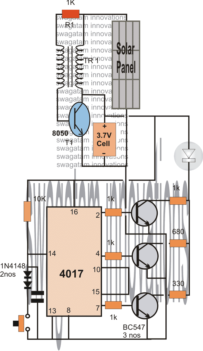
The Design

  • When an input is applied, the transistor instantly goes into an oscillating mode inducing a relatively stepped up voltage across the connected battery.
  • The process starts charging the battery and depending upon the position of the IC 4017 output illuminates the connected LED with a certain intensity.
  • The IC 4017 operates in three modes as requested above.
  • The modes can be selected by pressing the given button momentarily.
  • The above toggling sequences the output from the pin2 to pin7 in steps producing different glow intensities on the LED.
  • At the first pin out pin#3 (not shown) the LED shuts down completely as it's not associated with the switching network in anyway.

How to build the TR1 transformer?

The circuit is a simple joule thief circuit which is used as a boost charger or a step up charger. To get all the details of the TR1 transformer you an refer to the first design from the following article:

Joule thief Circuit

solarboostLEDwithDimmerCircuit

You'll also like:

  • 1.  Solar Battery Charger using LM339 Comparator
  • 2.  How to Calculate Solar Panel, Inverter, Battery Parameters
  • 3.  Self Optimizing Solar Battery Charger Circuit
  • 4.  Homemade Solar MPPT Circuit – Poor Man’s Maximum Power Point Tracker
  • 5.  PWM Solar Battery Charger Circuit
  • 6.  How to Make Dye-Sensitized Solar Cell or Solar Cell from Fruit Tea

About Swagatam

I am an electronics engineer with over 15 years of hands-on experience. I am passionate about inventing, designing electronic circuits and PCBs, and helping hobbyists bring their projects to life. That is why I founded homemade-circuits.com, a website where I share innovative circuit ideas and tutorials. Have a circuit related question? Leave a comment.... I guarantee a reply!

Previous Post: « Zero Drop LDO Solar Charger Circuit
Next Post: 5V 3 Amp Fixed Voltage Regulator Circuit using IC LM123 »

Reader Interactions

Comments

  1. Nelio Abreu says

    November 7, 2020 at 4:43 pm

    Hi Swag,

    What’s the value and type of the capacitor?
    Best Regards.
    Nelio Abreu

    Reply
    • Swagatam says

      November 9, 2020 at 8:34 am

      Hi Nelio, capacitor value can be 1uF/25V

      Reply
  2. Bibin Edmond says

    August 28, 2013 at 3:03 pm

    oh….! ok.. thanx swagatam.. !

    Reply
  3. Swagatam says

    August 28, 2013 at 6:57 am

    Hi Edmond,

    It's for enabling the switching only after at least 1V passes through push button as it's pressed, so that the IC responds only to legit pushes and not accidental leakages.

    Reply
  4. Bibin Edmond says

    August 27, 2013 at 6:06 pm

    Hi swagatam,

    what's the use of two 1N4148 diodes on the circuit.. ?

    Reply
  5. Swagatam says

    August 6, 2013 at 5:39 am

    You are welcome Ashutosh,

    TR1 is wound over a toroid type ferrite core with 20:20 turns of any thin super enameled copper wire.

    The switch is an ordinary push-to-ON type of switch or simply a push button which should switch ON only momentarily when pressed and disconnect when released.

    The boost circuit is explained here more elaborately:

    https://www.homemade-circuits.com/2012/10/1-watt-led-driver-using-joule-thief.html

    Reply

Need Help? Please Leave a Comment! We value your input—Kindly keep it relevant to the above topic! Cancel reply

Your email address will not be published. Required fields are marked *

Primary Sidebar


Subscribe to New Circuits

Categories

  • Arduino Projects (87)
  • Audio and Amplifier Projects (132)
  • Automation Projects (17)
  • Automobile Electronics (101)
  • Battery Charger Circuits (83)
  • Datasheets and Components (104)
  • Electronics Theory (143)
  • Free Energy (37)
  • Games and Sports Projects (11)
  • Grid and 3-Phase (19)
  • Health related Projects (25)
  • Home Electrical Circuits (12)
  • Indicator Circuits (14)
  • Inverter Circuits (87)
  • Lamps and Lights (142)
  • Meters and Testers (69)
  • Mini Projects (46)
  • Motor Controller (64)
  • Oscillator Circuits (27)
  • Pets and Pests (15)
  • Power Supply Circuits (108)
  • Remote Control Circuits (50)
  • Security and Alarm (64)
  • Sensors and Detectors (101)
  • Solar Controller Circuits (59)
  • Temperature Controllers (42)
  • Timer and Delay Relay (49)
  • Transmitter Circuits (29)
  • Voltage Control and Protection (37)
  • Water Controller (36)


  • Privacy Policy
  • Cookie Policy
  • Disclaimer
  • Copyright
  • Videos
  • Sitemap


People also Search

555 Circuits | 741 Circuits | LM324 Circuits | LM338 Circuits | 4017 Circuits | Ultrasonic Projects | SMPS Projects | Christmas Projects | MOSFETs | Radio Circuits | Laser Circuits | PIR Projects |

Social Profiles

  • Twitter
  • YouTube
  • Instagram
  • Pinterest
  • My Facebook-Page
  • Quora
  • Stack Exchange
  • Linkedin


  • © 2025 · Swagatam Innovations