Here's a simple triac timer circuit which can be used for switching ON a particular device after a predetermined time, set through the given pot or the variable resistor.
The shown circuit diagram of a simple triac timer can be understood by referring to the following explanation:
How it Works
The left hand side section comprising the IC 4060 becomes the basic delay generator stage. As we all know, the IC 4060 is an extremely versatile time delay generator chip which has a built in oscillator for the required fundamental timing clocks.
The components connected at the pin#9,10 and 11 form the time delay determining parts of the IC.
Precisely, the resistor at pin#10 and the capacitor at pin#9 are responsible for fixing the delay period and may be adjusted for acquiring the required predetermined switching output.
This IC has 10 discrete outputs which produce delays or oscillation periods which are twice to the previous pinout in the order.
Here pin#3 produces the largest delay, followed by pin#2 and then pin#1 and so on as per the specified pinout order. So suppose pin#3 produces delay interval of 1 minute, then pin#2 would produce the same at an interval of 30 seconds, pin#1 at 15 seconds and so on.
Since pin#3 is specified with the highest time interval, we use this pinout as the output.
Therefore suppose we set the RC at pin#9 and 10 with a maximum delay of 2 hours, pin#3 would be assigned to generate alternately changing ON/OFF pulses, having equal delay intervals of 2 hours, meaning initially the output would be OFF for 2 hours, then ON for next 2 hours and so on as long as its powered.
The above explains the IC 4060 configuration, now I have explained about the triac configuration.
As we can see, the output pin#3 is directly connected to the gate of the triac, while the triac A1 and A2 are terminated with the load and the other specified parameters.
When power is first switched ON, C3 at pin#12 of the IC4060 makes sure that the timing count initiates right from zero by resetting pin#12 with a short pulse.
The output pin#3 now initiates with a logic zero output while the IC internal timer starts counting.
Due to the logic zero, the triac stays switched OFF initially along with the load.
Once the predetermined delay interval lapses, pin#3 instantly becomes high, triggering the triac and the load.
The diode connected across pin#3 and pin#11 plays an important function of latching the IC counting process.
If this diode is removed, the counting process will continue and after 2 hours the triac will be again become switched OFF, and this procedure will go on repeating every after 2 hours.
The diode shuts off this operation, and lathes the IC to the ON position permanently.
The above situation provides us with another interesting application of the proposed circuit, by removing the diode we can convert the above circuit into an AC lamp flasher circuit, the flashing rate being set by the RC components.
Also note that irrespective of the RC parts you have the option of selecting/connecting the remaining outputs of the IC with the triac gate for getting a diverse range of time delays.
Circuit Diagram for Delay ON Timer
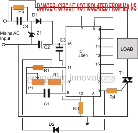
The above triac controlled timer circuit becomes suitable for applications which requires a delay switch ON.
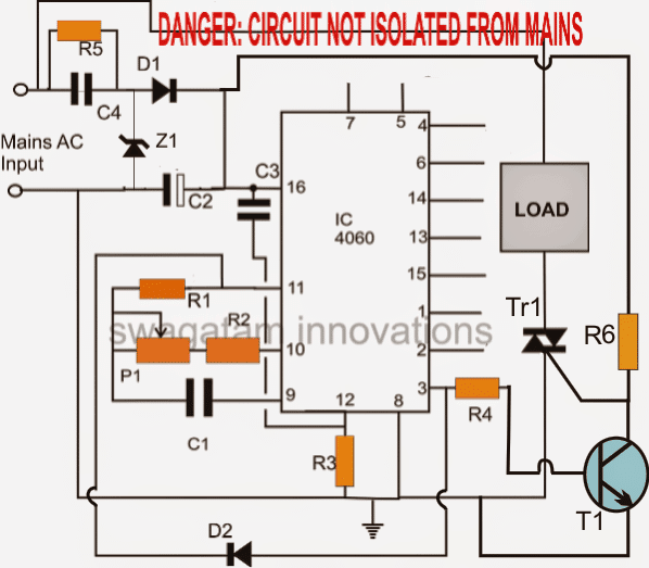
For applications which require a delay switch OFF meaning in cases where a load needs to be switched off after a predetermined time interval, the above circuit can be modified as given below:
Circuit Diagram for Delay OFF Timer
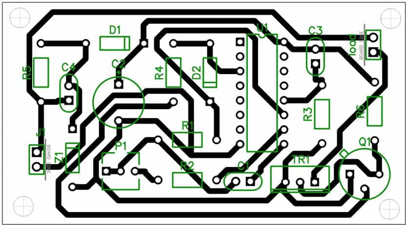
PCB Layout
Parts list for the above simple triac timer circuit
- R1 = 2M2
- R3 = 100K
- R2, R4, R6 = 1K
- R5 = 1M
- C1 = 1uF/25V (must be non-polar, use more in parallel for higher delays)
- C3 = 0.1uF disc
- C2 = 100uF/25V
- C4 = 0.33uF/400V
- Z1 = 15V 1watt zener
- Tr1 = BT136
- T1 = BC547
- D1, D2 = 1N4007
- P1 = 1M pot
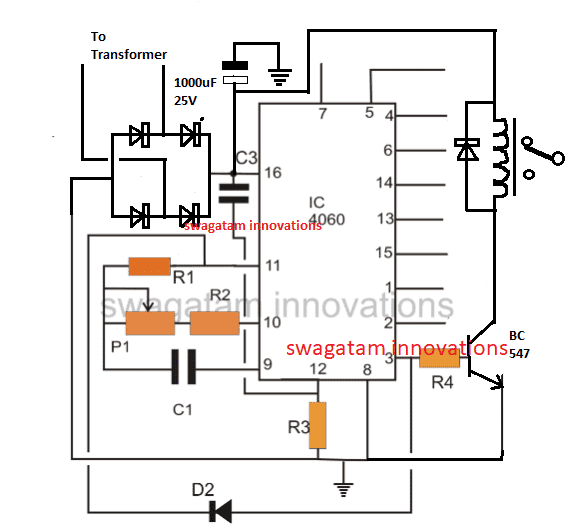
Using a Transformer DC Supply
The above simple timer circuit can be also built using a transformer DC supply, as shown below:
All diodes are 1N4007, and the relay is 12V/400 ohm, 10 amp


Mr Swagatam, thank you very much first of all.
I need a timer, that every 12 hours starts a 3 volt motor and can be reset (mechanically) to start the cycle again.
Is your first circuit suitable for this purpose? What are the R and C values for 12 hours?
(It is for a fish feeder)
I greet you gratefully.
You are welcome Mr. Rafael, 12 hours is a pretty long duration, therefore the timer should be also a long duration type.
You can try the second diagram from the following article:
https://www.homemade-circuits.com/how-to-make-long-duration-timer-circuit/
Muchísimas gracias por la respuesta!! probaré, agradecido.
Mr Swagatam, could you please publish circuit diagram for temp controlled soldering iron 12v dc or 230v ac
Thank you Rajesh, you can find some related info in the following link:
https://www.homemade-circuits.com/?s=soldering+iron
Alternatively you can use the 317 IC based regulator for controlling the 12V soldering iron
And use a triac dimmer circuit for controlling a 230V soldering iron
Hi!
I want to assemble the circuit at home. Where can I buy the PCB and components?
You can assemble on a piece of strip board or any general purpose board, PCB is not required for a prototype building.
Hi Dear,
Is there any triac circuit which can turn on/off appliances by cutting off mains and neutral both wires.
I know circuits which works by switching devices by cutting off only one wire i.e Phase wire and neutral stays conneted.
But sometime i can’t confirm the correct polarity of ac input to triac.
can you help ?
Hi, it can be tricky to use separate triacs across both LiVE/Neutral, but may be SSR could be used.
Hi mr swagatam..nice timer circuit..
Ive creat few dc timer circuit for my phone charger, im interesting with your ac timer, on my dc timer ive used 555 but Vin is not same with Vout, i try with BJC and its same result, than ive try with z44 smd and all smd for another components and its was great result to reach same V/I in out for time that i want (maks 3 hour)..but my problem is i need big Caps (4400uf) and its size too big for me..can you help me to resize the circuit or another tiny timer circuit?..any help would be great..keep the good works
Thank you Indira,
A 555 IC cannot be used for getting long duration timings with smaller capacitors. According to me using a single IC 4060 will do the job for you, with much smaller capacitor such 10uF (10nos of non-polar 1uF in parallel) and a 3M3 resistor.
Alternatively you can combine IC 555 with IC 4017 for the same results.
An example design is shown in the following link using IC 4060 and IC4017. You can replace the IC 4060 with IC 555.
https://www.homemade-circuits.com/how-to-make-long-duration-timer-circuit/
thaks for your kindness mr swag..hoppely it works as i need..keep the awesome works..
Thanks
It’s my pleasure Indira!
Hi mr swagatam..thank for your kindness..i forgot to ask you about the out put..is it same V&I output from the input?..because ive try another circuit on youtube and its not same on V&I. Hopely u can help me to choose from one of your lot of awesome circuits.
I need :
V =4.5v to 12v (same in&out)
I = >5amp
Small size componenents (no relay/transformer)
Time duration = 1-3 hour.
Once again thank you.
Hi Indira, yes, no doubt the output from a 4060 IC will be almost equal to the supply connected across its Vcc and ground (5V to 32V max).
The current will depend on the transistor rating that is used at the output of the 4060.
yes 1 to 3 hours can be easily achieved with great accuracy
Hello Mr. Swagatam, I have used the concept of your first circuit with a 555 to switch on and off my hot glue gun, 60W/230V, in order to reduce the high temp of silicone. Few secs ON and few secs OFF (dimmer didn’t help). I have an issue though. It burns the gate resistor 1K no matter of the resistors wattage. I use BTA16 700B triac that I have handy for the test. Any help would be appreciated.
Hello Than, the first circuit uses a IC 4060, so I am not sure which circuit you are referring to.
The 1K should never burn, because the triac gate will consume not more than 50mA, which can never burn a higher watt resistor.
Make sure the input supply is restricted to 12V for your circuit.
hello, you can use a monostable 555 IC circuit and connect its pin#3 to a triac in the same manner as shown in the first circuit above,
this set up will allow you to get the required delay as soon as the pin#2 of the IC is grounded via a push button
What is the p1 value
it's a potentiometer
Ideal ccts. Design.
????
can be a 1M
Checked out the circuit as suggested by you. Looks perfect for my application. One query- what is the value of potentiometer P1?
OK that's great, P1 can be a 100k pot, will depend on the time delay requirement
Ok. What will be the min and max delay time for 100K pot?
you will have to verify it practically or you can do the given formula here:
https://www.homemade-circuits.com/2012/01/how-to-make-simple-versatile-timer.html
C will be in Farads
Hello,
I made the circuit (the second one with transistor). Did actually somebody made and test this circuit? Without transistor the circuit works great, but with transistor I can not get the result. It only switch the load (40W lamp) on and after while when it should go off nothing happen. Even on pin 3 on IC there is no rising voltage. Have someone a solution? I have only one change T1 is BC183C and not BC547. Thank you for answer. Regards Kitchi
both the circuits should work equally well.
BC183 is OK and can be used.
connect a LED in series with the emitter of the transistor or in series its base…when this light up, the triac must go OFF, and vice versa,
this LED will indicate whether or not your transistor is switching correctly.
If the LED is not responding ON/OFF or if its permanently ON or OFF would indicate a faulty transistor or wrongly connected transistor..or a faulty IC
Hello, suddenly it works. Maybe there was a poor contact. Only one question more. When powering on and the load is on the load (light bulb 20W) is flickering for a 5-10 seconds and volt-meter also is showing ups and downs of the voltage on bulb (very quickly like 2 ups and downs per second) and after 10 seconds bulb is on normally like it should be-no flickering. Could it be defect triac (it is brand new) or voltage at the gate is not ok at startup? Kind regards Kitchi
try increasing the value of C2 to may be a 1000uF/25V…this will most probably solve the flickering issue….if that doesn't help increase the value of C4 to 0.47uF/400V
Hello. It takes some time sorry, Increasing C2 is not helping, increasing C4 is increasing power voltage more than 15V so Zener diode is limiting the voltage and I thing this is not good because it might be burned someday and the circuit may be damaged. And a little flickering is still there. I think that on the ventilator it won't be so disturbing as on the lamp. I thing I can live with that 🙂 .Thanks for help.
OK no problem but normally there should not be any kind of flickering, unless something's incorrect in the connections, or the parts.
….a 100uF/25V capacitor across collector/emitter of T1 might solve the issue…
Can I able to set 10s delay by using this ic 4060. In our college we did amicrocontroller based automatic bell one day we face a problem that relay stay in Nc position due to this bell rang for long period of time until we turned on the supply. In order over come this we have planned to add some extra time ic that even if the relay fails to operate the bell should be turn off after the 10s time delay. Can I use this circuit for it
this circuit may not be exactly suitable, you can try a 555 monostable configuration.
Sorry i'm a little confuse. Once and for all. Let me rephrase my question. What should i use for c1? a. 2-.68uf/50v mylar in parallel, or b. 1uf/50v?, what polarity of this capacitor should be connected to pin 9 of ic4060?
you can use any value, any type for C1, but it needs to be non-polar.
higher values will give higher timing delays
In your reply last Sept.20, you said 50v is enough for c1 (in the parts list it is 25v. i doesn't matter anyway,right?). My question is: what polarity of c1 should be connected to pin 9 of ic4060?
I'm sorry but i'm confused on your statement on what is the value of c1. Once and for all please kindly specify the value and/or rating of it? You said 50v would be enough for C1, at 1uf? What polarity should be connected to ic4060?
the voltage rating needs to be twice that of the supply volatge, as a rule of thumb…higher voltage rating will not do any harm.
when it's non-polar, there's no restriction to polarity, it can be connected anyway round.
Going back to c1 issue. Finally, it is a 1uf/50v electrolytic capacitor, right? Polarity please? What polarity should be connected to pin9 of ic4060?
C1 can be of any value, but it needs to be strictly non-polar…you can use many 0.68uF capacitors in parallel if non-polar 1uF is difficult to obtain.
higher values will give higher timing periods
Can i substitute the 1M pot with a fix value resistor? If your answer yes, what value would it be? I just wanted a simple 2 hours off and 2 hours on timer circuit.
yes you can….first insert any random value like 220K, and check after how many minutes the pin3 becomes high….once you get the result you can simply calculate other resistor values for any other desired timing through cross multiplication.
If i use two .68uf in parallel, will you specify a 250v value of it?
no…both should be 400V
I am sorry i confused it with the input cap…actually for C4,
50V would be just enough for C1
Therefore c1(1uf/25v) is a mylar. Can i just simply use .68uf(volt please) in replacement for the 1uf/25v? What do you mean use 'it in parallel?' and what is the value of the p1?
C1 can be any type of non-polar capacitor….you can put two 0.68uF or two 0.47uF capacitors in parallel to substitute the shown 1uF capacitor
P1 can be a 1M pot