This article is written with an intent to explain in detail behind the making of a simple surround-sound decoder circuit.
By: Dhrubajyoti Biswas
Overview
The concept of the decoder was first introduced by David Hafler in the 70s. His research illustrates the way to use two speakers as rear speakers on a surround system.
The figure below is a diagram based on Hafler’s research:
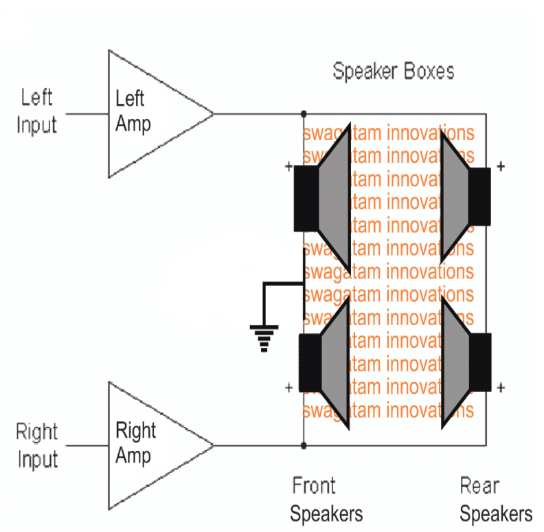
Figure 1
According to Figure 1, Hafler designed the circuit to enable the rear speakers generate the difference of signal between right and left output.
While every stereo encoded system maintains difference of signal between the right and left channel, it is that difference of signal when received by the rear speakers gets reproduced.
However, it is vital to keep in mind not to earth the negative terminals of the rear speakers, else the rear will behave parallel to the main front speakers.
Line Level Passive Version
Using individual amplifier for rear speakers is not actually possible. However, there is a way-out which we figured out after some research. Referring to Figure 2, it is totally passive, but it needs an ideal transformer – a transformer with impedance of 10K [1:1 ratio], which is quite rare to find, but available.
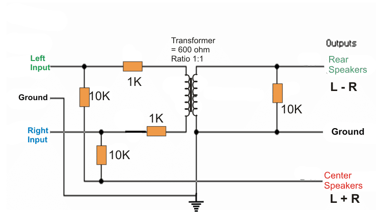
Figure 2
As an alternative we have tried using a 600ohm unit. But it is for the impedance the output we received was not good as it lacks bass.
However, upon loading the transformer, it increased the bass quality but the preamp doesn’t seem to work at its fullest because of the impedance. It is for this reason that we have used telephonic transformers with 600:600ohms, and it worked well.
The circuit in Figure 2 illustrates the way we followed. Following this design, it worked, but it has very low impedance on all cases barring solid-state preamp.
Using 600ohm unit, the loss generated is around 3dB. The low frequency is -3dB on 100Hz. However, it varies based upon the quality of the transformer.
600ohm telephony transformer is widely available in the market, but many of them are not up to the mark to use it in this experiment.
Most of the hi-powered transformers are sold in bulk and is therefore hard to procure a single copy. So, the alternative would be to use dual opamp to design the system, and its process is mentioned below in detail.
Explaining the New Circuit
The schematic diagram in Figure 3 gives a detailed view behind this development of the simple surround sound decoder circuit.
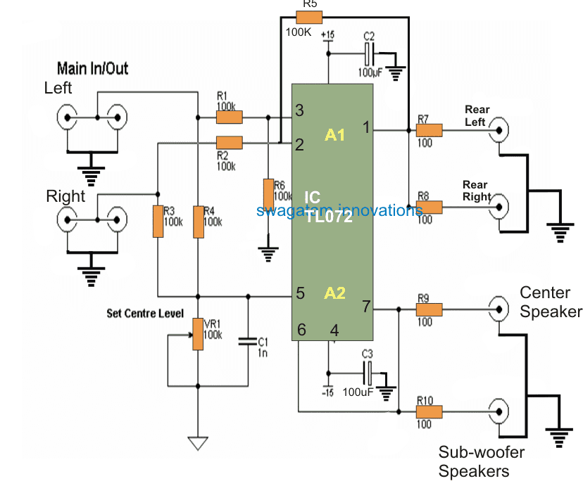
Figure 3
While the new design [Figure 3] will follow Hafler’s principle, this new circuit has simplified wiring, albeit we needed extra power amps. There is now a center channel signal and the sub-woofer to receive mono signal is also set.
You may have encountered similar type of circuit on other papers, but there are some twists into it. We avoided any active electronics on left/right channels and introduced opamps to zero down the factor that may cause degradation of sound.
The 50K impedance will not pose any barrier for a preamp, as the main signal is parallel to the additional circuit.
Extra volume control has been excluded from the system, because of the presence of volume control in the preamp. Moreover, the power amp of rear channel also has level control to balance the front and rear levels.
Please note, if you are following the circuit as in Figure 3 do ensure to make the rear speakers wired-out phase.
Let one speaker connect to the amp on a normal fashion and the second should be connected keeping the leads of speaker reversed.
Though the difference maybe negligible, but to derive the best quality effect it is always advisable to opt for out-of-phase connection. This helps in maintaining left-right and right-left signals.
The way surround sound decoder circuit works
A1 opamp should be connected in the form of subtracting amplifier, and if same signal is passed to both speakers, the result will be Zero.
This will result to removal of all information that are common from the stereo signal, and would produce the difference signal, similar to that of Hafler’s. A2 on the other hand is a summing amplifier. Its output has all necessary information from the left and right channels.
Center Channel Control
VR1 pot is set to level the center channel. It can either be a conventional pot or trimpot with the rear mounted.
Adding up the two channels [left / right channel] where signal is not mono, -3dB will be will be the level of center channel.
For instance, if the center channel speech is mono then the level becomes equal on both speakers. The possibility of amp overloading or the speaker is a rare case here, since the speakers and channel amplifier are not as much powerful compared to the left/right channels.
The sound of center channel does not need to be high. It has to be stable and the available level control is quite enough to generate required output.
The use of C1 Capacitor is not mandatory as it provides roll-off frequency of 8kHz. This actually helps to reduce any issues on the signal of the main stereo.
Output – Sub-Woofer
The output of the sub-woofer is taken from central channel mixer and added no-pass filter because it is hard to determine a sub where there is already a filter.
Other factors
100ohms resistors are used to block the oscillation of opamps by preventing the capacitance of the signal lead. Following this would not result to loss in frequency, but if you use 100m long signal leads, it may pose problem.
Referring to Figure 3, the rear speakers have two outputs in parallel.
The reason to do it is to enable easy wiring to facilitate connection of stereo amplifier with the rear speakers.
Normally, mono amplifier would do fine as long as it drives parallel to the two rear speakers. But this may not be feasible if you are using 4ohm speakers and if you do use it then ensure to connect them in the form of series. In order to enable out-of-phase connection, the red terminals need to get joined, and further connect the terminal of the speakers to the output of the amplifier.
Building the System
You can place the entire system on a metal case. Using metal case blocks the hum or other noise coming from mains etc.
While there is no factor of heat generation, you can use small case. However, ensure to maintain space to fit the RCA connectors and rest of the components.
Also, be sure to not to set the components loose as this may lead to short circuit.
You can wire the components and the dual opamp on a Veroboard. Also do ensure to apply 1% metal film all over it to lower the noise.
You may keep the RCA connectors hard-wired. Do ensure to check the earthing.
The power supply center lap and the RCA connectors should maintain secure connection to avoid noise pickup. You can also use 100uF polyester caps to connect with 100uF supply bypass capacitors in parallel, but this is not mandatory.
Delay Line
If you are planning to enrich the sound you can also apply delay line in order to delay the sound going into the rear speakers. But that is again not mandatory.
Overall, performance of your system is fully dependent on the way you have arranged the circuit. If the proposed simple surround sound decoder circuit is not well built you may face constant issues compared to a well-built one.


Comments
still persists…. and when power returns back the LED becomes brighter instead of turning off automatically…. so i am expecting a suitable solution from you for this…
sorry for a very long description about thia .. i have mailed the circuit your inbox… hitman2008… plz check ot out and respond to me as earlier as possible
Sir actually what happens in a less expensive surround sound system which doesnt utilize any types of dolby or dts decoding method ?
(1). Are the processes which these systems doing only addition and subtraction of stereo signals ?
(2). Are those hometheatre systems available in market at cheap rate ( below 5k or even 10k ) based on this principle or using correct decoding according to dolby algorithm ?
Sir one more doubt..
How to control the volume of the entire setup ?
you can feed the sound through a pot to the specified inputs and these pot can be used as volume controls
Sir i have 3 doubts in last circuit using TL072 IC
1). will the IC capable of driving 5 nos of 10 W speakers with maximum power output at extreme level of music ( maximum dB ).. i need distortion free working of these 5 speakers with maximum capable sound level without adding any noise into them and operate the subwoofer separately
2). can i add a separate amplifier section for a subwoofer of 100 W power rating at pin no. 6 of the IC TL072 for good bass ? for that can i use the circuit posted by you in this blog ?
https://www.homemade-circuits.com/2012/01/how-to-make-outstanding-home-theater.html?m=1
3). What is the maximum power output of the above mentioned home theatre system with subwoofer and one tweeter ? i can make decision about the selection of an appropriate subwoofer after hearing your reply
expecting your reply soon
HI RT, here are the answers:
1) the circuit is designed for 4 speakers only, not 5…and it needs to be attached with an external amplifier for powering the speakers
2) yes all the speakers will require amplifiers for the reproduction, the TL072 is only for processing, it cannot amplify the sound for the speakers directly…you can use any of the mosfet based amplifiers from this site for the sub
3)this will again depend on the amplifier wattage that you are supposed to use externally…