In this article I have explained a few simple infrared TV remote controlled fan regulator or dimmer circuits using ordinary parts such as a 4017 IC and a 555 IC.
The first concept uses a standard MOSFET based SSR for controlling the fan load and for easy and clean PWM signal operation from the IC 555 and IC 4017.
Audio/Video Representation
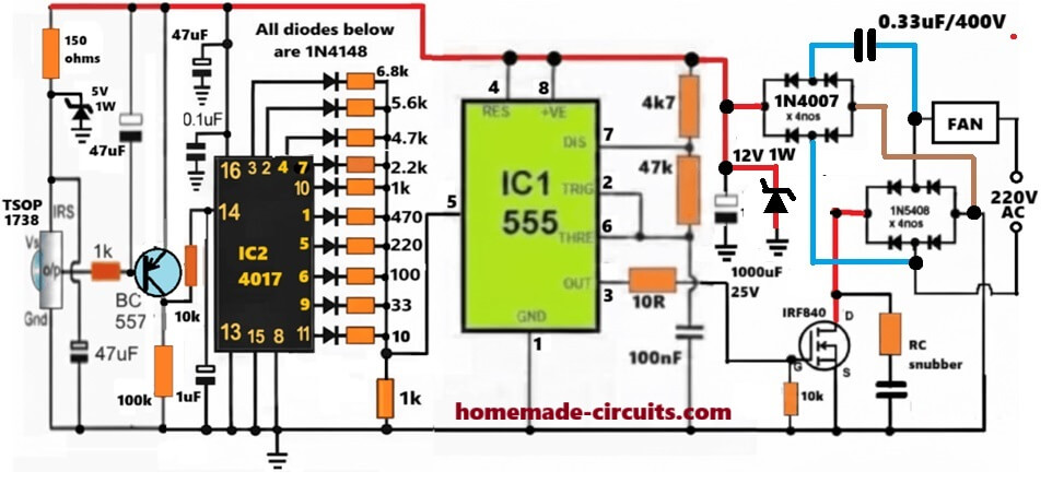
Fan Remote Circuit Using PWM Controlled MOSFET SSR
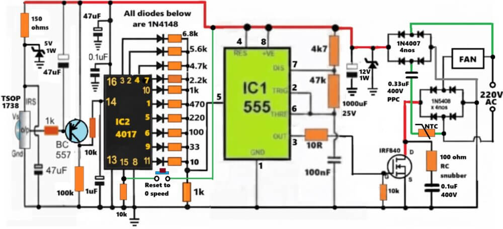
This fan remote control circuit does not rely on touch or push button, here we are using IR TV remote.
At first glance it looks heavy but actually idea is very simple.
Starting From Left Side… IR Part
So at the left side, we have TSOP1738.
Normally its output stays HIGH. When remote sends IR signal, then suddenly output goes LOW. That is how TSOP works, we all know it.
But problem is, TSOP output is not like one neat pulse. It is like a messy stream, depends on protocol, and how long button is pressed.
So we cannot just push that into CD4017 pin 14. If we do that, then fan might jump like crazy.
Why That BC557 Is Needed There
Now here comes BC557 and this part is important.
When TSOP pulls LOW, BC557 reacts causing output to become a short clean pulse. That is the whole job of the BC557 transistor stage.
Those resistors and capacitors around it, they are just slowing and shaping things.
So even if someone keeps pressing remote button, still only one pulse reaches CD4017 pin#14.
CD4017… The Memory That Moves Step By Step
Now CD4017 is configured to do its usual thing. Pin 14 gets a pulse causing output to move forward.
Q0, Q1, Q2, Q3… like that. Meaning only one output is HIGH at a time, always.
Reset pin is arranged so that after last step, it goes back to start. So the cycle never breaks.
This makes fan speed control predictable. The user always know where he is...
Diode + Resistor Network… Looks Messy But is Crucial
Now this part… many people misunderstand this.
Each CD4017 output goes through 1N4148 diode, then through a resistor. All resistors are different values. Then all of them join with the resistive divider 1k, and the junction goes to pin 5 of 555.
So what is happening?
Only the active output is allowed to push voltage, other outputs are blocked by diodes.
Different resistor divider with 1k means different voltage levels at pin 5.
555 Is Not Acting Like Normal 555
Now IC1 is 555. It is working in PWM mode.
Here Pins 2 and 6 tied, 47k and 4k7 are setting timing, Frequency mostly stays fixed.
But pin 5 is being pushed up and down by that resistor ladder. So threshold levels move causing duty cycle to change.
So when we press the remote button, the 4017 output sequences up/down causing the PWM ooutput from the IC 555 to vary, which in turn causes the MOSFET switching vary accordingly.
The MOSFET varying switching causes the fan speed also to becomes faster or slower depending on which IC 4017 output is selected, and the corresponding 555 PWM duty cycle level applied to the MOSFET gate...
It simply means, Duty cycle change = fan speed change. That is the real trick here.
Gate Drive And MOSFET Side
Now the PWM comes from pin 3 of 555. Before reaching IRF840 gate, it passes through 10R resistor.
We can also see a 100nF capacitor and 10k pull-down.
These things helps to calm the signal. Without these, MOSFET can behave badly, especially with mains AC voltages.
Now as we can visualize IRF840 is not switching AC directly. AC is first rectified using 1N5408 bridge. Then MOSFET chops DC.
That is why fan runs smoother compared to triac dimmers.
Protection Elements
The RC snubber, 0.33uF/400V capacitor, 15V zener, all these are there because fan motor is inductive. Inductive loads kick back voltage. If you ignore that, MOSFET dies slowly or suddenly. So these parts help absorb spikes, reduce noise, and keep things alive.
Concept using Triacs and Opto-Couplers
Now let us look at the next design below, which uses a triac for switching the load or the fan.
Referring to the shown remote controlled fan dimmer circuit, three main stages may be seen incorporated: the infrared signal sensor stage using the IC TSOP1738, the Johnson's decade counter, sequencer using the IC 4017 and a PWM processor stage using the IC 555.
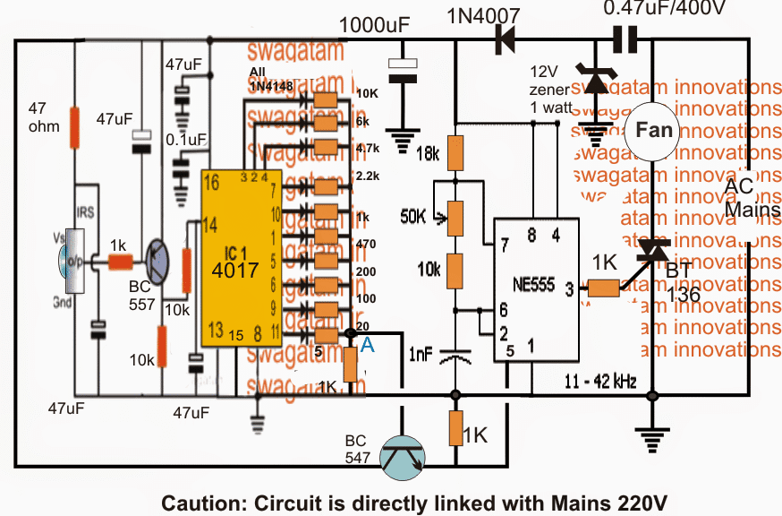
The various operations involved within the circuit can be understood with the help of the following points:
When an infrared beam is focused at the sensor, the sensor produces a low logic in response to this which in turn causes the PNP BC557 to conduct.
WARNING: THE ENTIRE CIRCUIT IS DIRECTLY LINKED WITH THE MAINS AC, OBSERVE EXTREME CAUTION WHILE TESTING THE CIRCUIT IN POWERED POSITION
UPDATE: You may also like this article on a Simple Ceiling Fan Regulator Circuit
Using Sensor TSOP1738
The sensor used here is a TSOP1738, you can learn more about it in this simple IR remote control article
The conduction of the BC557 transistor in response to the IR beam links the positive supply to pin14 of the IC 4017 which is accepted as a clock pulse by the IC.
This clock pulse is translated into a single sequential hop of a high logic from the existing pinout to the next subsequent pinout in the sequence across the shown outputs of the IC 4017.
This sequential transfer or shift of a high logic pulse from one pinout to the next across the entire outputs from pin#3 to pin#10 and back is carried out in response to every momentary beam focused on the IR sensor by the IR remote handset.
Using IC 4017 for Controlling Voltage Divider
We can see that the IC 4017 outputs have a set of precisely calculated resistors whose outer free ends are shorted and connected to ground via a 1K resistor.
The above configuration forms a resistive potential divider which generates a sequential incrementing or dropping potential levels at the node "A" in response to the shifting of the high logics across the outputs as discussed in the above explanation.
This varying potential is terminated at the base of an NPN transistor whose emitter can be seen connected to pin#5 of IC 555 which is configured as a high frequency astable.
Using IC 555 as PWM Generator
The 555 stage basically functions like a PWM generator which varies proportionately as its pin#5 potential is varied. The varying PWMs are created at its pin#3.
By default pin#5 is connected with a 1K resistor to ground which ensures that when there is no voltage or minimum voltage at pin#5 results in an extremely narrow PWMs at its pin#3 and as the potential or voltage at its pin#5 is increased the PWMs also gain width proportionately. The width is maximum when the potential at pin#5 reaches 2/3rd of the Vcc of its pin#4/8.
Now apparently, as the outputs from the IC 4017 shifts creating a varying voltage at the base of the NPN, a corresponding amount of varying voltage is transferred over pin#5 of the IC 555 which in turn is converted into an accordingly changing PWMs across pin#3 of the IC.
Since the pin#3 of the IC is connected to the gate of a triac, the conduction of the triac is proportionately influenced from high to low and vice versa in response to the changing PWMs over its gate.
This is effectively converted into a desired speed control or an appropriate regulation of the connected fan across the triac's MT1 and the AC mains input.
Thus the speed of the fan becomes adjustable from fast to slow and vice versa in response to the infrared IR beams toggled on the associated IR sensor of the circuit.
How to Set up the circuit.
It may be done with the help of the following steps:
Initially keep the emitter of the BC547 transistor disconnected with pin#5 of the IC555.
Now the two stages (IC 4017 and IC 555) can be assumed to be isolated from each other.
First check the IC 555 stage in the following manner:
Disconnecting the 1K resistor across pin#5 and ground should increase the speed of the fan to maximum, and connecting it back should decrease it to minimum.
The above will confirm the correct working of the IC 555 PWM stage.
The 50k preset setting is not crucial and may be set to approximately center of the preset range.
However, the capacitor 1nF could be experimented to get the best possible outcomes. Higher values up to 10uF could be tried and the results monitored to achieve the most favorable fan speed regulation.
Next, we need to check whether the IC 4017 output node at "A" creates a varying voltage from 1V to 10V in response to each pressing of the IR remote beam over the circuit's IR sensor.
If the above condition is met, we can assume the stage to be functioning correctly, and now the emitter of the BC547 can be integrated with pin#5 of the IC555 for the final testing of the fan speed regulation using a IR remote handset.
The remote handset could be any TV remote control which we normally use in our homes.
If the above design does not work smoothly with a connected fan, it may need to go through a slight modification for improving the results as shown below:
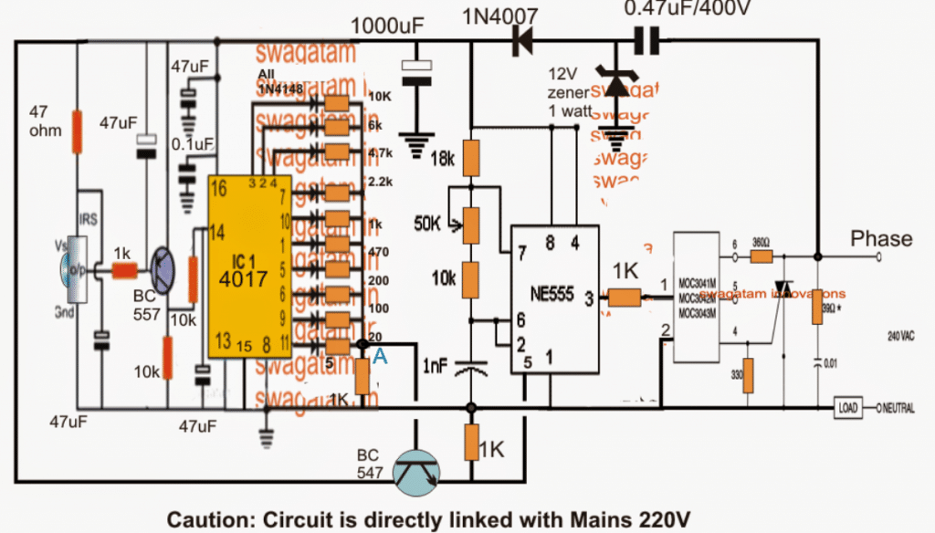
The circuit takes the help of a MOC3031 triac driver stage for enforcing a hassle free and clean fan control through the remote handset.
Test Analysis
On testing the above circuit, the results were not quite satisfactory, since the fan could not be controlled upto the lowest limit and it showed some vibration.
Analyzing the design revealed that the application of PWM on triac was causing the issue since triacs do not respond well to DC PWMs, rather show improved reactions to AC phase chopping as used in dimmer switches
Using Phase Control instead of PWM
The circuit discussed in this article eliminates the PWM idea for the fan dimming control, instead employs few low power triacs for sequentially implementing the dimming or speeding effect on the connected fan motor.
The complete design for the proposed remote controlled fan dimmer circuit can be witnessed below:
Circuit Diagram
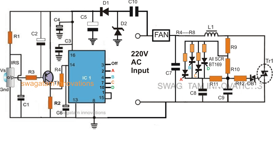
Note: the 4 SCRs are incorrectly represented as SCR BT169, these must be replaced with triacs, such as BCR1AM-8P triacs, or any other similar triac will also do.
How it Works
Referring to the diagram above we can see two the circuit configured across a couple distinct stages.
The right side of the diagram is configured as a standard light dimmer or fan dimmer circuit, except one change, which can be seen near its usual pot section, where it has been replaced with four triacs having four separate resistor at their MT2, arranged with an incrementing values.
The left side stage comprising the IC 4017 is wired as a 4 step sequential logic generator, triggered by an Infrared sensor unit which forms the IR receiver for receiving the switching triggers from a hand held IR remote control unit.
The alternate remote IR beams from IR transmitter causes the IRS to generate a toggling pulse at pin#14 of the IC 4017, which in turn converts the pulse into a sequentially shifting logic high pulse across its pin#3 to pin#10 after which it's reset back to pin#3 via pin#1/15 interaction.
The above pinouts which are responsible of generating a sequentially traveling logic high pulse are serially connected with the gates A, B, C, D of the indicated triacs.
Since the resistors connected with the anodes of the triacs become the determining components for the fan speed limit, implies that by sequentially switching the triacs to and fro, the speed of the fan can be increased or decreased proportionately, in 4 discrete steps, depending on the values of R4----R8.
Therefore when the remote handset button is pressed, the IC 4017 pinouts trigger the corresponding triac which in turn connects its anode resistor with the dimmer triac/diac configuration, executing the relevant amount of fan speed.
In the proposed remote controlled fan dimmer circuit, 4 triacs are shown for producing a 4-step speed control, however 10 such triacs could be implemented with all the 10 pinouts of the IC 4017 for acquiring a good 10 step discretely controlled fan speed regulation.
Parts List
R1, R3 = 100 ohms,R2 = 100K,R4 = 4K7,R5 = 10K,
C2 = 47uF/25VC1, C4= 22uF/25V,C6 = 4.7uF/25V,
C3 = 0.1, CERAMIC
C5 = 100uF/50V
C10 = 0.22uF/400V
T1 = BC557
IRS = TSOP IR sensor
IC1 = 4017 IC
D1 = 1N4007
D2 = 12V 1watt zener
R9 = 15K
R10 = 330K
R4---R8 = 50K, 100K. 150K, 220K
R11 = 33K
R12 = 100 ohms
Diac = DB-3
TR1 = BT136
L1 = 500 turns of 28SWG over any iron bolt.
C7 = 0.1uF/600V
WARNING: THE ENTIRE CIRCUIT IS DIRECTLY LINKED WITH THE MAINS AC, OBSERVE EXTREME CAUTION WHILE TESTING THE CIRCUIT IN POWERED POSITION



Discussion & Solutions
Have you tested MOSFET circuit yourself? MOSFET dimmers are not suitable and safe for induction fans. I want to run home ceiling fan but triac based circuit produced humming sound.
MOSFETs can work nicely with inductive loads if the protections are applied correctly…the above MOSFET has a snubber and gate zener diode, so it won’t have any issues with inductive loads like fan…you can also put a parallel TVS diode with snubber for enhanced protections.
Triacs cannot work with PWM that is why a MOSFT is used here..
I have searched web again, and found lot of views regarding MOSFET dimmers not suitable for induction motors like ac ceiling fans. I am sceptical about trying this. That is why I want to know if someone has tried this MOSFET dimmer for ceiling fan.
If you operate MOSFET with inductive load, and without protections, then definitely it will burn…
I NEED A HELP
PLEASE SUGGEST WHICH REMOTE USE WITH THIS CIRCUTE DIGRAM
You can use a TV remote or an AC remote…
Its cool, sir is it possible to add rf module in this circut instead of ir?because through ir all remotes will work, plz provide me full diagram with rf module plz
Thanks Ghulam, This circuit has not been tested by me, so i would suggest you to first test the effect of 555 pwm output on a ceiling fan or a table fan (with start capacitor, not BLDC). If the fan responds well to the 555 PWM then the rest of the circuit can be quickly built and attached with the 555 circuit for the remote control working….
You can use an IR module also with this circuit.
sir i tried with 334j 400v, 10k 2watt in parllel with capister, then used 12 volt zenor 1 watt, then with positive supply used in4148, then 1000uf 25 volt capister, but 10k resister goes heat. plz guide me where is the problem? or can we used 12 volt power supply?
Hi Ghulam, 12V 1 watt zener is fine, it will work.
You can also use an external 12V DC power supply but that will be unnecessarily bulky.
If your 10k 2 watt is heating up, please modify the power supply section in the following manner:
sir i tried this circut, i checked with 220volt cooler water pump, speed is not much fast, and also there is no fan off level, fan is continually on in low speed also…..fan should be off nd on from remote also plz
Thanks Ghulam, To ensure the circuit is working correctly as intended, you will have to check every section of the circuit with an oscilloscope because PWM waveform testing and confirmation is very important here. Unless all the stages are verified with an oscilloscope you can’t confirm if the circuit is build correctly or not.
To get a switch off function, you can keep pin#3 open (disconnected). But the problem is that you cannot switch off quickly with one button press, because pin#3 sequence will arrive only when all the 10 pins of the 4017 are switched. One idea is to use only 5 outputs instead of 10, so that the sequences become short and quick, and anyway 10 step speed is actually never required.
Thank you sir, I will modify and update you, sir with capister 10k resister is not draw in diagram, in this logic 10k resister in parallel of capister not required or we have to use?
Sure Ghulam, no problem, yes now 10k resistor is not required, because the capacitor can discharge through its own bridge rectifier.
We can copy the capacitor based commercial regulator ckt . By understanding the capacitor combinations for different speeds, we can make our own speed control by using 3 small Spdt pcb relays……which does not create power line noise and better for fan(no humming noise at low speeds)
Yes, that’s correct! Glad you understood the circuit well.
Sir,
REMOTE CONTROLLED, CEING FAN MODULE: 0.1 uf/600 v capacitor is not available. 1000 v is available. will it be ok? Further, can we add one light connection to this module (with same features)?
Hello Katrtikeshwar, 0.1uF/1000V will work, or 0.1uF/400V will also work. Light can be added, but the light should be incandescent bulb type, LED light will not work.
Hello sir
How are you sir?
Sir can I use any IR receiver in place of TSOP 1738, which I have the remote control unit.
Hello Mekuz, TSOP is reliable since it works with 38 kHz signal only, other IR can be affected with any light source
Dear Swag,
Sorry to bother you again. Can I use any type of TSOP
Receiver Sensor?
Will it work?
yes you can use TSOP, but the transmitter frequency must match its specifications…
Dearest Swag.
May the good Lord bless you richly for your selfless service to all of us.
I may not have what to give to compensate you or your family for your great contributions to humanity
but God will bless you and your generation in Jesus name.
I am indeed grateful.
No problem Mekuz, I am always happy to help!
Dear Swag.
Thank you for everything and your time and efforts to
help me. I am indeed grateful.
Please sir in you said the L1 should be 100 turns of 22swg on a ferrite rod
what is the length and diameter of the ferrite rod?
Or is there no ready made inductor that I can purchase? If there is please what is the value of the inductor?
Thanks in advance
Dear Mekuz, the L1 is not critical, use any number of turns over any ferrire core, and monitor the RF noise on any AM radio, you can put more turns until the noise becomes minimum…
Dear Swag,
I am a bit confused. While I am trying to solve the math that may have led to
the values of the resistors of the Transistor BC557, I had to ask some questions to clear my doubts
and confusion.
Please is the Transistor configuration a Common Emitter connection? Or A common Collector Connection?
I could figure out how the values of its resistor where made R3, R4, and R2
Hoping to hearing from you soon
Thanks you sir.
Dear Swag,
I was trying to calcualte how you got the values of R3, using
the formula Rb or (R3) = 0.2 × RL × hFE
where hFE is 300max, RL is 100K as shown in the circuit
But the answer I got is quiet different from the value you gave to R3
I got 6,000000 ohm but your says 100ohms
pls help me to correct my errors
Thanks
Dear Mekuz, when you walk on the road with a bag, do you calculate how much weight your bag can have? You can have 1 gram load or 2000 gram load in your, you don’t bother about it…similarly it is not always required to calculate electronic circuit unless the parameters are critical.
For a 400 ohm relay, the base resistor needs to be 56k, but I always use 10k, so it is not a critical factor.
Dear Swag,
Please I know am bothering much, I want to know so of the exact functions
of C2, C3, C4 and C6 in the circuit and mode of operation.
Why did you place C6? How did you choose the R4 to be 4K7.
I am curiously waiting for your response.
Thank you in advance
Dear Mekuz, that can be a lengthy tutorial, not possible to explain through comments….you will need to learn the designing process step wise.
Hello Swag,
Please I have a question on the operation of the IC 4017
By connecting pin#1 and pin#15 together for reset, will it make the counter count to 9 then reset?
Please enlighten me here sir.
I am facing my defence soon.
Please explain to me the operation of the triacs and diac in regards to this circuit.
Pls if there are mathematical relations in getting some of the values of the components in this circuit show me too.
Thank you very much sir.
I will forever be grateful.
Hello Mekuz, yes, that is right….. you can also use all the 10 outputs by connecting the pin15 with ground
How to Understand IC 4017 Pinouts
The diac fires once the voltage across it reaches 30 V, this 30 v timing is determine by the RC network connected with the diac….with the RC network delays the diac firing, it delays the triac firing resulting in slow fan speed, if the RC network is adjusted for quick charging discharging, then the diac keep firing at a faster rate, causing the triac to react faster, and this increases the fan speed…
Diac – Working and Application Circuits
Pls sir, I cannot get this BCR1AM-8P in my place.
Is there no alternative that is common.
Are all capacitors polarized?
Mekuz, you can try optocoupler triac:
https://www.onsemi.com/pdf/datasheet/moc3072m-d.pdf
feed the 4017 output triggers to the opto LED, and the opto triac can be used across the indicated positions, in the fan regulator circuit
Hello Sir,
Can you verify these resistors for me.
Which of them is actually meant to be in the circuit.
R1, R3 = 100 ohms,R2 = 100K,R4 = 4K7,R5 = 10K,
R4—R8 = 50K, 100K. 150K, 220K
in the list you highlighted R4, R5 twice and they are of different values
which of them will I use
Hello Mekuz, the values are correct, only R4 is repeated in the diagram, yes they have different values.
I hope you know how to test the circuit stage-wise and step-wise, because if you test it by connecting all the parts together, the circuit will definitely have problems and also something might burn.
Dear Swag,
How are you sir? Hope you are great.
Please sir the pin#3 pin#5 Pin#6 pin# 9 pin#11 and pin#12
are they to be left unconnected?
Thank you for your time, energy and understanding.
Dear Mekuz, all those pins of the IC 4017 are outputs which are not used, so you can keep them all unconnected!
Thank you sir. You are the best
My pleasure Mekuz!
Dear Swag,
I am indeed grateful for the timely response.
May the good Lord bless you.
Thank you sir. My regards to your family.
No problem Mekuz, I hope you are able to make it!
Please sir I am totally confused. I need urgent help. In the circuit diagram, you said we should replace the BT169 with BCR1AM-8P triacs, then if so show me the new circuit diagram when the BT169 are replaced.
You equally included BT136 in the list of the components where does it fit in in corrected circuit diagram.
Thank you.
Mekuz, you just have to replace the BT169 with BCR1AM-8P, with pin#1 going towards C8/R11 and pin#2 towards the upper series resistor
BT136 is the main triac TR1
Moreso, the equivalent of the inductor L1
L1 = 100 turns of 22 swg super enameled copper over any ferrite rod
Good day Swag,
Please what is the value of the capacitors C8, C9
Again what are the equivalent of the triac and diac
C8, and C9 can be 0.033uF/250V
Hello sir,
I got 0.33uf/275v for C8 and C9. instead of the proposed 0.033uF/250v
Please will it work or it must be 0.033uF/250v?
Thanks
No it will not work…
Hello Swagat,
I am sorry to bother you a bit.
In regards to Remote Controlled fan circuit incorporated with 433mhz transmitter and receiver circuit
Please can I have the PCB, along side with the components of the aforementioned project. Or already made and tested by you. It will ease my work and time to submit the project. How much will it cost me sir?
I want to pay for it.
I am looking forward to hearing you soon.
Thanks in advance.
Hello Mekuz, I am sorry, providing a PCB design or a ready made kit will not be possible from me due to lack of time.
By the way this project is not easy, unless the user knows exactly how to test and verify the different stages, completing this project can be hugely difficult, so please proceed with caution!
Thank you sir. You are amazing.
Mekuz
Glad to help Mekuz!
Dear Swagat,
I really want to say a big thank you for this project.
I am a student and am currently working on 433mhz RF remote control for a fan.
Please sir how can this your project work with 433mhz RF transmitter and receiver instead of the IR in that your circuit?
Please sir I need your urgent help
Thank you for your time and efforts.
Mekuz
Dear Mekuz, yes it is possible. You can do it by simply removing the sensor stage, and connecting the 433MHz receiver output with the pin14 of the the IC 4017
Please sir where is the transmitter circuit of this remote? What I can see is receiver circuit
The remote control can be any TV remote handset, …any button
Dear Swagat.
Thank you for your prompt response. I am glad to hear that is possible.
However sir, I will go ahead build it and incorporate it with your rf 433mhz circuit.
I will update you as I progress. If need be I would like to purchase the already constructed circuit from you.
Hope I can get them?
Thanks
No problem Mekuz, let me know if you have any issues with the circuit
i am looking for a circuit where two bulb and one fan speed would be controlled , if you design any circuit about this please send me in email
Do you want to control them together or separately?
Want to control in same circuit, where fan speed control using volume plus and minis button and two light switching any other button
Will investigate it, and update the results if it’s feasible
Hi sir,
I like this product but what value of resister 470,200,100,20,5 ………ohm / k and 1000mfd / ?….v
Hi Vipul, those are in Ohms.
I would recommend the last circuit, that’s more reliable.
awesome project Sir, Want to learn more from here.
you are most welcome!
I have a rechargeable fan with 12V 7AH battery, I wanna integrate a remote controller and solar charge capability
Hello Mr.Swagatham,
I was working with above IR remote control Fan circuit with bit small modification near resistor values of IC CD4017 outputs,
The circuit flow as mentioned,, TSOP1738–>CD4017–>555–>MOC3041–>BT136–>Triac–>Snubber–>FAN..
1.The fan control with duty cycle variation is working fine,
2.The fan is working fine at 0% duty cycle and 100 % duty cycle,
3.If the duty cycle is >10 % and <90 % the fan is wobbling /Arcing,i.e the fan is trying to rotate in opposite direction during the PWM OFF time, Since the fan is rotating in forward direction initially, during the PWM OFF time it will try to rotate in opposite direction,that means there was flickering or jurrking kind of rotation was foreseen,
4.So kindly suggest us the possible solution to overcome this kind of problem,
Thanks and Regards
Bl Gowda
sorry BL, there's no easy method to solve it, the only way to correct it is by applying a time proportional PWM as explained in my previous comment.
Hello Mr.Swagatham,
Thanks for your inputs,
Sorry for asking the same question again,
Basically i have tried using the TSOP1738–>CD4017–>555–>MOC3041–>BT136–>Triac–>Snubber–>FAN..method,
Since i had tried using the above method to drive the FAN, i am trying get some solution for the stuttering effect,
Now i have used MOC3063, the stuttering effect is reduced(but still observed very less),is there any other possible option to to reduce or drive the fan smoothly,
Thank and Regards
BL Gowda
Hello Mr. Gowda, as updated at the beginning of the article, the concept has some flaws which needs to be corrected, because triacs don't respond to PWMs in the way transistors do.
For controlling a triac with PWM we may have to employ a special technique called time proportional phase control, which I have elaborately explained in the following article:
https://www.homemade-circuits.com/2016/10/triac-phase-control-using-pwm-time.html
In order to apply the above concept in our present circuit you may have to employ an astable 555 stage after the PWM stage so that the MOC inpu can be fed with a train of pulses instead of a constant long PWM for driving the triacs. This process will hopefully execute a proper speed control of the fan and also stop the stuttering effect.
Or alternatively you can employ the following concept which simply gets rid of this complex process and works with additional triacs for the intended speed control of the fan very smoothly.
https://www.homemade-circuits.com/2016/09/remote-controlled-fan-dimmer-circuit.html
alright, i'll get back to you as soon as i verify them myself.
Mr. Swagatam, i got a friend to build the circuit and its not responding to remote control. i used a bulb in place of the load. the bulb turns on as expected but there is no dimming effect. i read though the comments and i saw what you told Orrie. i tried that one too and also put in the MOC3031 but still no dimming effect. i even got some other friends to look at it, but they couldnt get it to work. what do i do now?
Hi Papin, you must confirm the working of the various stages first separately.
first check whether your IR sensor stage is working or not…if it is working correctly then check whether or not the IC 4017 is responding to the toggling from the sensor at its pin#14.
once these are confirmed then you may proceed to check the IC 555 PWM stage.
this is the way how all circuits must be verified.
Mr. Swagatam, i was looking at your circuit diagram and i couldnt recognise the type of capacitor you used connected to the 1n4007 diode. am referring to the 1000uF capacitor.
Mr Papin, it's rated at 25V, and it's electrolytic
Hai, Could u make a circuit for a ceiling fan speed controller with a 7 segment diaplay(to show the speed 1-9 stages of the fan) and two push-to-on switchs for up-down speed control?
Hi, yes I remember I'll try to do it soon…using LM3915 IC and 555 IC
Hi, Just an reminder for my request. If the fan speed control with a 7 segment is too complecate means up-down momentary switchs with 7 speed control with 7 LEDs will also fine for me.
Hi, if possible I will try to post it soon.
Mr. Majumdar,
Would you please mention the following as early as possible?
a) All the resistors' – Watt ( 1/4 or 1/2 or 1)
b) Capacitor – 47 Micro-farad and 0.1 Micro-farad – is polarized ? Vol ?
Regards,
Mr.GHosh, all the resistors are 1/4 watt
47uF/25V is polarized but 0.1uF/50V is non-polar.
Mr. Majumdar,
Thank you for your comments. However, I have seen in the room of my friend a single remote switch which is used for controlling both a fan ( Speed) and a light ( ON/OFF) by a single remote control.
The remote switch has four connecting points. One for AC input , one for AC negative, one for fan, one for light. Remote is same.
Could you please post/e-mail a circuit diagram showing the above arrangement.
Also, let me know where can I get the PCB.
Regards,
DK Ghosh
E-mail: dkghosh5555@gmail.com
…or it might have employed a circuit similar to this:
https://www.homemade-circuits.com/2013/07/simple-100-meter-rf-module-remote.html
Mr.Ghosh,
what you are referring could be am embedded type commercial circuit, I have made the design using discrete components so it's not possible to make it compact like the commercial ones.
Sir please send me an automatic fan regulator circuit diagram using LM35
I'll try to update the design in my site…possibly soon.
Thanks Swagatam.
Hi Swagatam,
Can I use LM567 and a photodiode instead of TSOP?
Shouldn't we use a diac between 555 and triac?
thanks,
Vijay
Hi Vijay,
the fan is supposed to work with an AC, so zero crossing effect will be present for the fan. If AC was not used then the zero crossing protection would become irrelevant. in any case both optos work with PWMs so the overall response should be the same from both the devices..
Hi Swagatam,
As far as I have read, optocouplers with zero-crossing wait for zero crossing which never happens in this circuit. Or at least that's what is my understanding. I'm not an engineer so I may be wrong but that's what I came across. If I ever get the opportunity to fully test your circuit again, I'll try again with a zero-crossing optocoupler.
Thanks,
Vijay
Hi Vijay,
I appreciate your efforts, however, It's important to identify why a particular concept is giving problems, without identifying the fault it can be meaningless to say it doesn't work or didn't work.
So you should first find out the exact technical reason why it's working with MOC3021 and not with MOC3061?? MOC3061 has a zero crossing detector and looks more advanced than MOC3021 so it should work with this IC too…unless there's a specific reason which needs to be identified.
Hi Swagatam,
I tried the circuit in a breadboard but fan did not run. Now I tried another circuit and that didn't work too. In the end I found that we must use an optocoupler without zero-cross detection. I first tried with an MOC3061 which I already had but it didn't work. I bought an MOC3021 which is a random-phase optocoupler and it works as expected. We need to play around with the resistor values to get the desired speed though.
Regards,
Vijay
Hi Vijay,
yes LM567 with photo diode can be tried.
diac is not required for a DC based triggering…it's applicable for AC based triggering.
it means remote to be pressed continuously. or press and release and press?
press, release, press…..each press will enable 1 step up in the sequence
Sir.mane circuit try kiya lekin rc network par 0.01mfd ciramic cap burn ho ja raha he.konsa cap use kar na he? Plz suggest.
use a 0.01/400V PPC capacitor…
dear sir how the full speed and slow speed can be achieved? when the remote is keep pressing it will speed up? then how getting slow speed?
the sequence will go cycling from 0 to max, then back to zero…so in order to come back from the middle to some lower point, the sequence will need to be taken to max so it can revert to zero and then to the desired speed level.
sir
can i use moc3021.
yes you can use it.
give trouble To access in your website.
now it's been fixed
thanks sir for your contribution.i am waiting for this.
I have updated it, you may check it out now.
I'll do it by tomorrow…..
sir i change 1nf to 1uf.the out put lamp was flashing.dimming effect was not change.then i try 103,104,271.but result was same.i thing this is the problame in sine wave.becaus i connect a led in pin 3 of 555.led dimming effect was perfect when i trigger ir its change high to low.but this thing was not happend in ac lode.
orrie, I think in that case we may have to integrate an opto isolator triac driver between pin3 of IC 555 and the triac
optoisolator such as a MOC3031
I'll try to upadte the diagram soon.
sir.
i am useing 12v smps adapter.how can i solve the problem? when i check this with a led or lamp the result is ok but when i connect with a motor it's not proper work..plz suggest me..
for simply switching ON/OFF a particular appliance, the following design may be tried:
https://www.homemade-circuits.com/2012/02/how-to-make-simple-infra-red-remote.html
Mr. Ghosh, if your requirement is to control the intensity of light then of course the above circuit can be used for the same (together with fan, or individually), otherwise you might have to build different units for the lights and the fan….although the remote handset can be the same.
Mr. Mazumder,
Thank you for your prompt reply. However, would you please confirm whether speed control of fan and controlling of one or two lights from the same circuit is possible?
Regards,
orrie, try increasing the value of the 1nF capacitor of IC 555 to 1uF…if still it gives problems then we may have to find some other option…
first check this and let me know.
sir,
mane circuit ko fan se connect kiye.speed varying accurate nahi hay.minimum speed per motor jerk horaha he.plz help…….
is the problem arising with an adapter or with capacitive power supply?
sir,nothing change with this improvement.
try a 1K/10 watt resistor, in place of the 0.47uF capacitor, but it will become quite hot…if still it doesn't work then try a 105/400V in it's place.
thanks sir,
circuit is working proper with 12v smpa.But when i connect with cap power it is not working.is proper carent is not their?
orrie, replace the single 1N4007 diode with a bridge rectifier and put the zener diode across the positive negative of the bridge, check the response with this improvement
sir
thanks for your valuable suggestion.as soon as possible i will check this.unfortunatei am just depart for election duty.after this i must be build this.with your blessing and you and your famaly blessed with a large fortune and good health.
you are welcome, orrie!
sir,
i am try to make this.Tsop1738 working fine but 4017 output volt was not vary when i trigger the ic.and pwm also not working.testing with 100w lamp.plz help
….you can replace the pin14 capacitor of IC 4017 from 47uF to 1uF for quick response at the outputs
you'll need to test it step wise,
initially do not use an AC input or bulb. feed a 12V DC from an ac/DC adapter to the circuit.
connect a red LED in series with the BC557 between its collector 10k resistor and ground.
this LED must light up and shut off in response to the input IR beams from the TV remote.
If the above happens the 4017 output will surely shift from one pin to the other, you can confirm this using a meter set in DC volts.
the above operation will create a varying voltage at the node marked as"A" confirm this also.
next confirm the same at the emitter of the BC547.
finally confirm whether the output of the 555 IC is generating the varying average voltage from 1 to 10V in response to these operations or not.
once all these are confirmed you can restore the circuit with the AC mains and the bulb for the intended results