• Skip to main content
  • Skip to primary sidebar

Homemade Circuit Projects

Need circuit help? Post them in the comments! I've answered over 50,000!

Blog | Categories | About | Contact | Calculators-online
You are here: Home / Timer and Delay Relay / Simple Kitchen Timer Circuit – Egg Timer

Simple Kitchen Timer Circuit – Egg Timer

Last Updated on January 2, 2024 by Swagatam 7 Comments

A kitchen timer is a useful gadget which produces an alarm sound after a predetermined delay, as set by the user for specific time based food recipes that must be cooked only for a certain amount of time for best results.

Table of Contents
  • How it Works
  • How to Calibrate

Written By: Suneeta Dixit

One example is boiled eggs which may be either hard boiled, medium boiled or soft boiled depending upon how long it is allowed to boil.

For such applications, a kitchen timer can be quite handy, and will provide the user with a warning alarm after the stipulated time is elapsed, so that the user can shut off the flame and avoid the food from getting overcooked or for getting the right desired texture and taste on the food.

kitchen timer circuit

How it Works

The kitchen timer circuit with alarm or an egg timer I have explained in this article could be built very cheaply, and it features an adjustable delay time setting between 1 minute and 17 minutes.

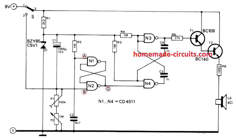
Other time ranges may be possible through little alterations. Initially while the circuit is not powered, capacitor C1 and C2 are uncharged.

As soon as the unit is turned on with switch S (position 1), input A of the flipflop N1 /N2 stays temporarily at '0V', to ensure that output Q of N2 turns into 0 and multivibrator N3/N4 is disabled. Next, capacitor C1 begins charging through potentiometer P1 and P2.

Once the voltage at point B becomes lower than the flipflop's switching threshold, the flipflop toggles and this initiates the multivibrator action.

This initializes the square wave frequency from the multivibrator which is amplified by the transistors T1 and T2 and the resulting tone output is reproduced through loudspeaker L.

When the kitchen timer is switched OFF (S moved to position 2), capacitor C1 begins discharging swiftly via resistor R1 to ensure that, once the timer switched on again for the next cycle, no left over charge remains in the capacitor which may otherwise cause reducing the timing length.

How to Calibrate

1. Adjust P1 at the center of its journey and adjust P2 to its minimum setting range. After that readjust P1 to allow a period of 1 minute.

2. Next, set up P2 to its maximum possible range and determine the time interval generated from the circuit.

3. Lastly calibrate the scale of P2 with a linearly increasing scale from a range of 1 minute minimum, and the maximum which was determined practically earlier.

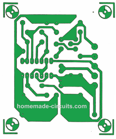
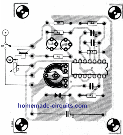
PCB Design and Component overlay

kitchen PCB track
kitchen pcb comp layout

You'll also like:

  • 1.  Simple Timer Circuit Using IC 4060
  • 2.  Timer Controlled Exhaust Fan Circuit
  • 3.  Make this Drag Race Timer Circuit
  • 4.  3 Stage Timer Circuit for Industrial Camshaft
  • 5.  Water Saving Irrigation Circuit
  • 6.  How to Make a Classroom Debate Timer Circuit

Filed Under: Timer and Delay Relay Tagged With: Kitchen, Simple, Timer

About Swagatam

I am an electronics engineer and doing practical hands-on work from more than 15 years now. Building real circuits, testing them and also making PCB layouts by myself. I really love doing all these things like inventing something new, designing electronics and also helping other people like hobby guys who want to make their own cool circuits at home.

And that is the main reason why I started this website homemade-circuits.com, to share different types of circuit ideas..

If you are having any kind of doubt or question related to circuits then just write down your question in the comment box below, I am like always checking, so I guarantee I will reply you for sure!

Previous Post: « Car Warning Tone Generator for Ignition, Headlight, Turn Lights
Next Post: Gadgets to Protect Women from Assaults and Harassment »

Reader Interactions

Comments

  1. jorge roble says

    January 12, 2022 at 5:11 pm

    Good day Swagatam, thanks for the post. it is very interesting and useful. I just have a question, since I only have one CD4011, and I dont know if it is in proper working conditions. I would like to ask if i can use CD4017 instead CD4011. Thanks again for the article.

    Reply
    • Swagatam says

      January 12, 2022 at 5:42 pm

      Thank you Jorge, you only require one 4011 IC for this project. However, 4017 cannot be used in place of 4011 since the two are entirely different CMOS ICs.

      Reply
  2. Marvin Manuel says

    February 9, 2021 at 12:36 pm

    Swagatam… I request you ckto to reverse the 3 / 4hp single-phase motor turn… start right for 5 mints, stop 1/2 sec and start opposite turn for 5 mins…
    and so on for a while … washing machine type, maybe digital analog … thanks

    Reply
    • Swagatam says

      February 9, 2021 at 1:52 pm

      Thank you Marvin, I’ll try to update the washing machine motor design soon in the washing machine article

      Reply
  3. Marvin Manuel says

    February 7, 2021 at 11:48 am

    Man, the subject is excellent and very necessary…. At the output you could put a relay … the combination of the flip flop and the multivibrator is very good and the times can be lengthened or shortened … the magic is the digital-analog hybrid, I am fond of electronics …. I’m looking for a timed reversal turn for 10min, stop 1sec, reverse turn 10 min, stop 1sec and continue… like the washing machine… maybe there is something in the rest of the timers…. I congratulate you very well on your website … greetings

    Reply
    • Swagatam says

      February 7, 2021 at 5:52 pm

      Thanks friend for liking and appreciating my work! I am glad you found the article useful! Please keep up the good work!

      Reply
      • Mohamed sobieh says

        November 8, 2021 at 4:05 am

        Thanks for this timer I think it could be utilized with 1 or 2
        LM 4017 to lengthen the time

        Reply

Need Help? Please Leave a Comment! We value your input—Kindly keep it relevant to the above topic! Cancel reply

Your email address will not be published. Required fields are marked *

Primary Sidebar


Subscribe to New Posts

Categories

  • Arduino Projects (88)
  • Audio and Amplifier Projects (132)
  • Automation Projects (17)
  • Automobile Electronics (101)
  • Battery Charger Circuits (83)
  • Datasheets and Components (104)
  • Electronics Theory (143)
  • Free Energy (37)
  • Games and Sports Projects (11)
  • Grid and 3-Phase (19)
  • Health related Projects (25)
  • Home Electrical Circuits (12)
  • Indicator Circuits (14)
  • Inverter Circuits (88)
  • Lamps and Lights (142)
  • Meters and Testers (69)
  • Mini Projects (46)
  • Motor Controller (64)
  • Oscillator Circuits (27)
  • Pets and Pests (15)
  • Power Supply Circuits (108)
  • Remote Control Circuits (50)
  • Security and Alarm (64)
  • Sensors and Detectors (101)
  • Solar Controller Circuits (59)
  • Temperature Controllers (42)
  • Timer and Delay Relay (49)
  • Transmitter Circuits (29)
  • Voltage Control and Protection (38)
  • Water Controller (36)

Tags

Alarm Amplifier Application Arduino Automatic Battery Charger Circuits Control Controlled Controller Current Datasheet DC Detector Digital Driver Electronic Explained Explored Generator High Indicator Inverter Lamp LED Light Meter Motor Pinout Power Regulator Remote Sensor Simple Single Solar Supply Switch Timer Transistor Voltage Water Watt Working


Other Links

  • Privacy Policy
  • Cookie Policy
  • Disclaimer
  • Copyright
  • Videos
  • Sitemap


People also Search

555 Circuits | 741 Circuits | LM324 Circuits | LM338 Circuits | 4017 Circuits | Ultrasonic Projects | SMPS Projects | Christmas Projects | MOSFETs | Radio Circuits | Laser Circuits | PIR Projects |

Social Profiles

  • Twitter
  • YouTube
  • Instagram
  • Pinterest
  • My Facebook-Page
  • Quora
  • Stack Exchange
  • Linkedin


  • Recent Comments

    • Swagatam on 10 Useful Active Filter Circuit Diagrams Explored
    • Swagatam on Treadmill Motor Speed Controller Circuit
    • Swagatam on IC 741 Power Supply Circuits
    • Swagatam on Simple Capacitive Discharge Ignition (CDI) Circuit
    • Paul Hess on 10 Useful Active Filter Circuit Diagrams Explored

    © 2025 · Swagatam Innovations