This BQ7718 series 2S to 5S series Li-Ion cell charger is designed to monitor the voltage of each of the li-ion cells independently, with reference to an internally set reference level.
As soon as any of the cell voltage tends to go above the reference level, it triggers an internal delay timer. This delay timer waits for a few seconds and then subsequently triggers ON the output pin of the IC.
The output of the IC shunts the input supply so that the over-voltage condition of the cell is quickly restricted.
The following diagram shows the basic configuration using 5S or 5 series Li-Ion cell pack:
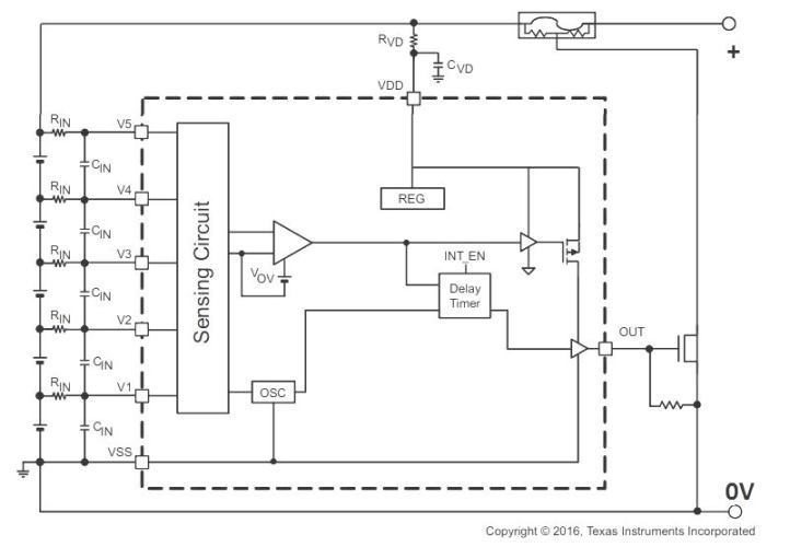
The supply input could be from a solar panel controller.
As soon as any of the series cell reaches an over voltage situation, first the delay timer activates, and waits for a while, and then ultimately the OUT pin is triggered ON to shunt down the supply.
The repeated OUTPUT ON/OFF switching allows the other cells to continue the charging process, and also simultaneously keeps the fully charged series cells from overcharging.
Over-voltage Protection of Series Li-Ion Batteries
Rechargeable batteries are commonly used for storage of the electrical power and to use that power as per demand.
The key challenges in battery operated systems are the overvoltage and overheating of the batteries.
Li-Ion batteries become a viable candidate for electronic industry and replacing the nickel-based rechargeable batteries.
Lithium-ion rechargeable batteries has gained popularity in last few years due to their extensive utilization in electric scooter, e-bikes, drones, and electric vehicle (EV).
The attractive and unique characteristics of Li-Ion batteries are:
- High energy density
- High Output Power
- High Cell Voltage (as compare to nickel batteries)
- Low rate of self-discharging (1:4 as compared to nickel technology)
Despite of having number of benefits over nickel batteries, the Li-Ion batteries are less tolerant, and overcharging reduces their life cycle.
The overvoltage and overcharging could lead to overheating, high internal resistance, low energy storage or even exploding.
To get the maximum benefits and to increase the life cycle of Li-Ion batteries the issue of overcharging must be addressed.
For the safety and protection of the batteries the protection circuits must be properly designed and integrated system with battery.
Overload and short circuit protection are also a vital factor for the prolong life of the battery system.
Key Features:
To combat with all above mentioned challenges, the experts have recommended the BQ7718 IC based series Li-Ion cell protection circuit.
The BQ7718 products range not only monitor the overvoltage in battery charging system, but also protect the battery pack from overvoltage.
As the battery pack consists of a series or number of cells, the protection of each cell has been ensured by the BQ7718xy circuits.
The application of BQ7718 has the flexibility to monitor and control the 2-series to 5 series cell Li-Ion batteries.
The overload and short circuit protection are also provided with the internal delay timer for the quick protection of battery cells.
The BQ7718 provides the customer test module and enables the independent monitoring of each cell to ensure the protection against the over voltage.
In customer test mode the test time can be reduced for the checking and verification of the overvoltage timer parameter while integrating in the battery pack.
To enable the test mode and configuration of delay timer please refer the data sheet.
Its size is small (QFN 3mm x 4mm, MSOP 3mm x 5mm) and economical enough to be easily incorporated into the battery pack.
Moreover, the operating voltage and current consumption of BQ7718 is too small (Low power consumption ICC ≈ 1 µA) that it can be lower than the inherent self-discharging rate of any well-designed Li-Ion battery.
The overcharge threshold is also fixed which allow the full charge and prevent the overcharging. It has the overvoltage protection with high accuracy of ±10 mV.
The range of overvoltage protection threshold can be selected from the catalogue (ranging from 4.200 to 4.300 volts) depending on the circuit requirement of the battery pack.
If the threshold selected is too high, the battery can be damaged, so select the threshold accurately as per the circuit need.
According to manufacturer, it is also important to note that the input of leakage current per cell is less than 100 nA.
Charge equalization in each cell is mandatory to store the maximum amount of energy, each cell should be charged equally.
Any imbalance in the charging of each cell due to manufacturing defect or frequent charging, discharging can reduce the operation time of the battery.
As we mentioned, in BQ7718xy each cell is monitored independently, the problem of cell imbalance charging can be eliminated.
The actual voltage and protection reference voltage is constantly monitored by the BQ7718xy for each cell, any detection of imbalance or unequal charging (configured OV delay time) among the cells activates a timer circuit.
When the timer circuit expires, the charging state is activated. The normal charging mode has been activated when the voltages fall below the preset values.
It has been recommended by the manufacturer that to sense the input voltage of each cell a series resistor and capacitor across the cell must be fitted as its required for the filtration of noise and stable monitoring of voltage.
The functional temperature of BQ7718xy ranges between -10 °C to 110 °C, exceeding these ranges may damage the devices permanently.
Prolong exposure to maximum limits in any condition may alter the functionality of the system and the reliability can be affected.
To avoid the reliability issue, it is recommended the devices should not be exposed to worst or maximum limit conditions for longer duration.
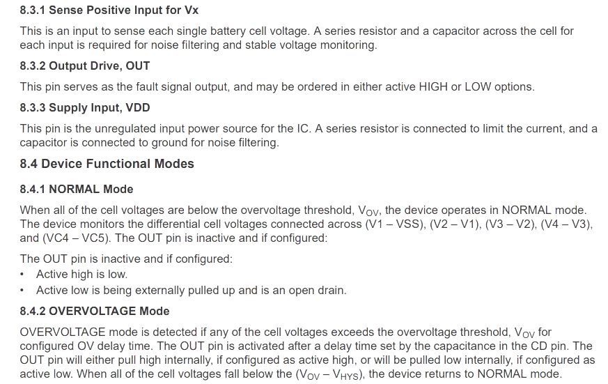
PIN functionalities:
The BQ7718xy is available in two common configuration packages like DPJ and DGK (both in 8 pins) as shown in below picture.
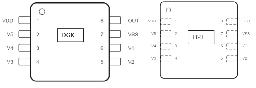
VDD is the power supply (30 V max, while 25V is recommended) while VSS is the reference ground or negative terminal.
A series resistor must connect with VDD to limit the current and capacitor should be connected to VSS pin to filter the noise.
V1 to V5 pins are used for sense input voltages in cell 1 to cell 5 respectively. Out pin is used for overvoltage (voltage range -0.3 to 30) fault signal in battery pack.
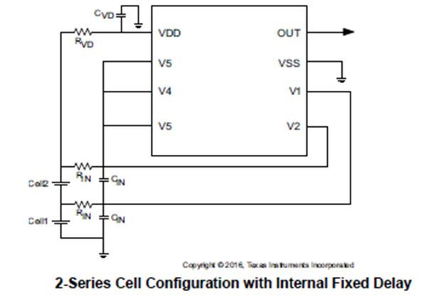
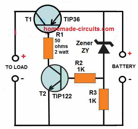
Circuit Configurations
A simple approach for the charging protection of 3,4 or 5 series cells of Li-Ion batteries has been shown in below figure.
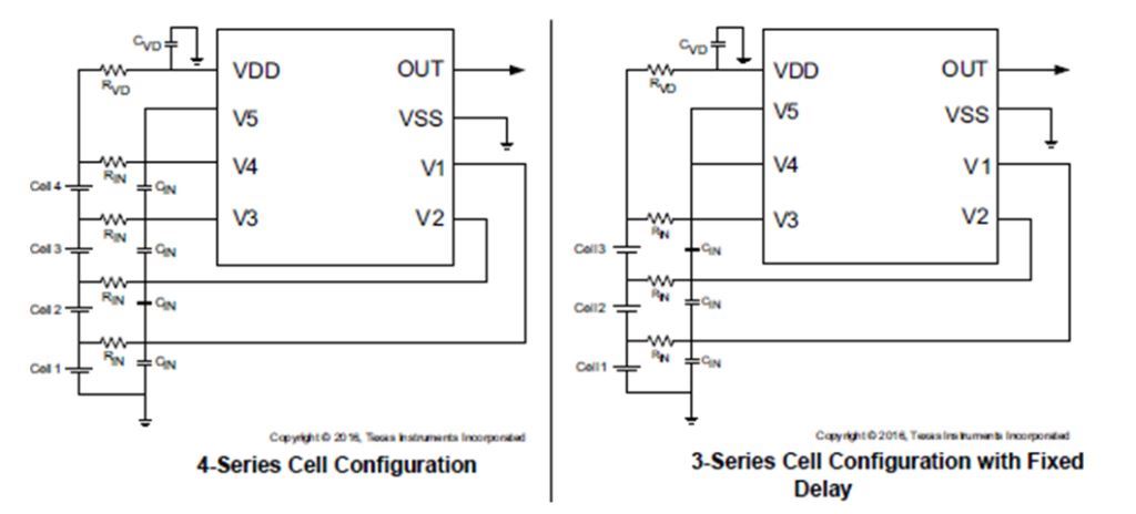
The manufacturer’s recommendations shall be followed for the development of overvoltage protection circuits for battery pack.
Any alteration in ranges stated in data sheet may impact the accuracy of the cell’s voltage measurement. The calibration of device has been done using value = 1 kΩ, the accuracy of device can be changed if other value of is used for calibration.
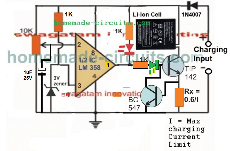
Application Circuit of BQ7718:
Electronic circuits for overvoltage monitoring and protection, charge equalization at high temperature condition with an internal delay timer can be designed by utilizing the BQ7718xy.
For the protection of Li-Ion battery packs utilized in handheld power tools/garden tools, electric bikes / scooter, and cordless home appliances like vacuum cleaner.
Summary:
The information presented in the image below provides the functional details of the IC and its application in a nutshell.
References:
https://www.ti.com/lit/ds/symlink/bq7718.pdf
Affanni, A., Bellini, A., Franceschini, G., Guglielmi, P., & Tassoni, C. (2005). Battery choice and management for new-generation electric vehicles. IEEE transactions on industrial electronics, 52(5), 1343-1349.


Need Help? Please Leave a Comment! We value your input—Kindly keep it relevant to the above topic!