For multi-storey buildings where water tanks could be at considerable heights over building terraces, monitoring the levels automatically could become a major issue. RF remote control modules have become pretty cheap nowadays which could be effectively used for solving the inconvenience. I have explained how to make and install a wireless water level controller circuit for the same, requested by Mr. Sriram kp.
Technical Specifications
I am planning to implement this circuit for my home over tank. Because I am in 1st floor and tank is in 5th floor. In the above circuit, Instead of the push switches in the transmitter section,
if i arrange the terminals D0-D3 inside the tank means, as the water rises, the one by one D0-D3 will get in contact through the water and this will transmit the signal to the receiver. So the output LEDs in the receiver will turn on according to water level.
In transmitter, suppose D0 is the tank empty state means there will be no contact to none of the terminals inside the tank, so the LED in the D0 of receiver will turn off, at this state the motor should turn on.
After the water level starts rising, the D3 of the transmitter will get contact , so the D3 LED of receiver will turn on
At this state the motor should turn off.
Please provide me the circuit for this...
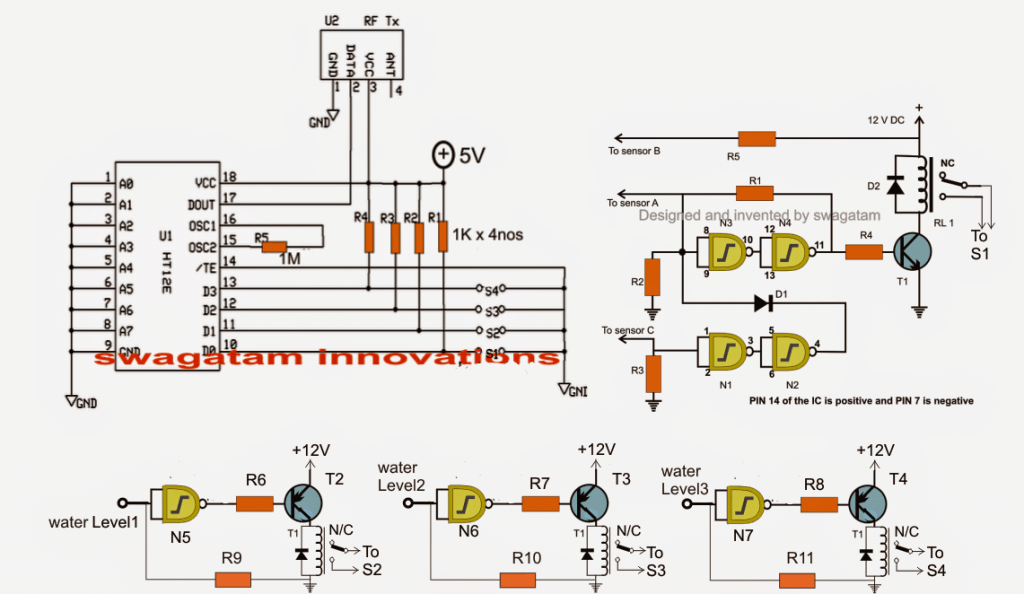
The Design
The circuit may be understood as given under:
Here we incorporate two separate stages, one is our automatic water level controller circuit and the other is the RF remote control circuit.
Using Tx, Rx 433MHz RF Modules
The remote control has a Tx (transmitter) and and Rx (receiver). The transmitter is triggered through four discrete switches which encode and transmit the signals discretely into the atmosphere.
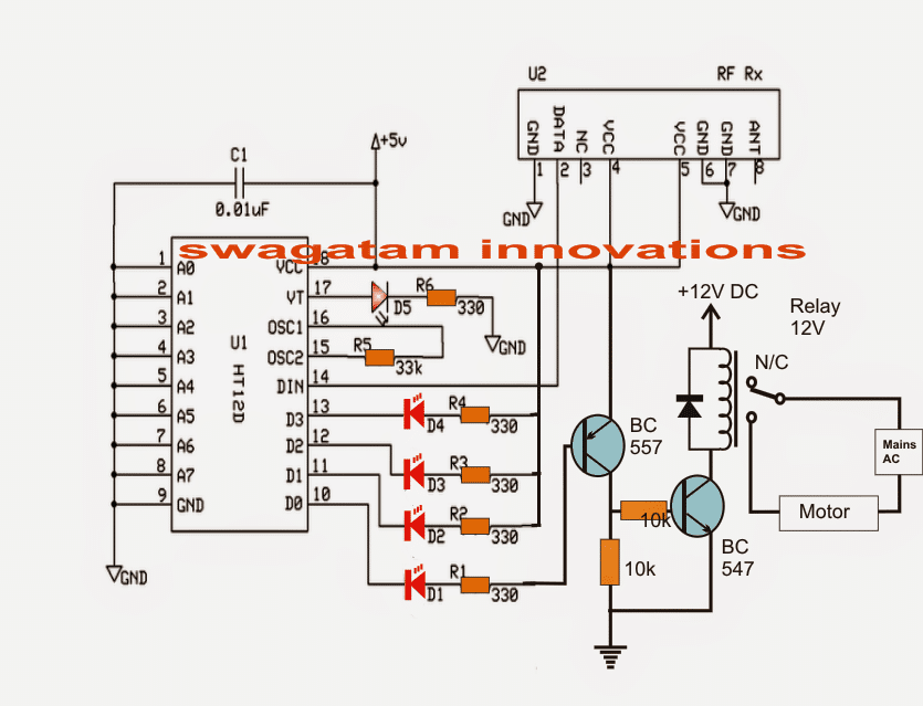
The receiver captures these signals, decodes it and sends it to one of the four outputs relevant to the decoded info.
This output responds by becoming high as long as the corresponding Tx switch is kept depressed.
The idea of the proposed water level controller through a remote control module is to press the Tx switches via relay contacts actuated by the water level controller circuit in response to the various water level conditions, as configured by the user.
The same has been implemented in the discussed design.
Referring to the figure, the gates gates N1 to N4 form the automatic water level controller circuit wherein the motor is switched ON when the level reaches a minimum lower threshold, and is switched OFF as soon as the level reaches the brim of the tank.
Originally Relay R1 was used for activating the motor by wiring its contacts to the motor and mains.
However for the present application, RL1 is rigged to one of the switches of the Tx module (S1)
Meaning now the Tx pin10 is engaged with the transmission of the signals as soon as RL1 is energized which happens on detection of an empty water tank.
Once this happens, the Rx responds by receiving the signals and triggering its own relay connected with the corresponding pinout.
This relay then activates the distant underground or overhead motor for the required water pumping.
The circuit diagram also shows three gates N5, N6, N7 which are configured as NOT gates for sensing the different water levels across the tank while the water is being pumped.
In the course these gates activate their own relays, which in turn close S2, S3, S4 for the necessary transmissions from the Tx to Rx.
The above transmissions are appropriately collected by the Rx, decoded and fed across its relevant outputs for illuminating the connected LEDs.
These LEDs provide the user with the info regarding the gradually filling water tank.
Thus the remote controlled triggering feature of the water level controller facilitates the owner a wireless and hassle free option of monitoring and controlling a distant situated tank.
The following figure shows the wiring details of the Rx or the receiver stage responsible for the toggling of the pump motor and various water level indications, in response to the Tx triggering signals.
Receiver Schematic
The RF modules can be sutudied in detail below:
https://www.homemade-circuits.com/2013/07/simple-100-meter-rf-module-remote.html
Parts List for the water level controller stage (N1----N4):
- R1 = 100K,
- R2, R3 = 2M2,
- R4, R5, R6, R7, R8, R9, R10, R11= 10K,
- T1 = BC547,
- T2, T3, T4 = BC557
- D1, D2 = 1N4148,
- All RELAYs = 12V, 400 OHMS, SPDT, contact amps as per load specs.
- N1, N2, N3, N4, N5, N6, N7 = IC 4093 (2nos.)
The last unused gate (N8) input must be terminated to ground or (+), output may be kept open.
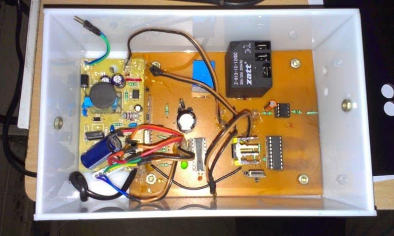
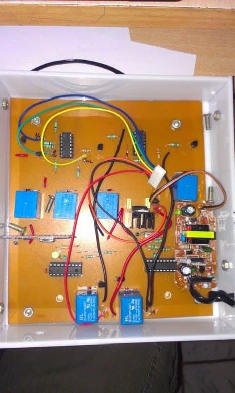
The above wireless water level controller circuit was built and successfully tested by Mr. Sriram kp. The following images exhibit the results of his outstanding efforts:




Questions & Answers
Hai, Thankyou very much for the circuit… One doubt, In receiver section, the relay is connected 12v and the transistor and all connected with 5v. will it wont create short circuit??
Thanks, no it will not create any short-circuit anywhere, if you intend to use a 5V relay, you could eliminate the BC547/10k stage and connect it directly at the collector of the BC557.
Thankyou, I like to connect another 5v relay in the receiver section. So can I connect that in the same BC547?? or do i need any extra components to connect 5v relay??
Hai, In RX section, if I dont want the LED at D0 means shall i remove the LED and 330 ohms resistor and connect the D0 directly to base of BC557??
And Is the below circuit diagram is correct to connect a 5v relay to BC557??? Is that 10k and grounded is needed?? or is that enough to connect the collector of BC557 directly to 5v relay without 10k and gound??
imgur.com/ALw0hi9
you can use it directly in place of the 12V relay, no modifications would be required.
You can remove the LED but not the resistor, keep the resistor as it is.
The relay connection is incorrect in your diagram….put it right in the place of the 10k resistor and remove the 10k resistor, meaning simply replace the relay coil with the 10k resistor position (collector and ground)
the monostable link that you have shown is OK, you can use it.
I modified. check whether the below circuit is correct to operate a 5v relay from the docoder IC?
imgur.com/jHk45S7
no still not correct, one lead will go to collector other to ground.
how abt now???
imgur.com/q7x5e2F
it's correct now, include the relay diode also
ok. Thankyou…
Hi swagatam hope ur doing good. I need ur help in making this circuit . I need to clarify couple of things from tx and water level circuit.
1. Which type of sensor is used in tx circuit
2. Can u plz mention the pin no of not gates in water level circuit
Hi Hafeez,
the sensors are just wire ends of the extended terminals appropriately tinned with solder and immersed at the relevant depths.
please refer to the datasheet of the IC 4093, you will able to see all gate pinouts in the given diagram, which you can directly apply for the above design
Swagatam what does water level 1 ,2,3 means in water level controller ckt.
I can't see 1, 2, 3 do you mean A, B, C??
In water level ckt , n5 n6 &n7 u have mentioned water level 1 ,2 and 3 , to be precise the input of not gates where does it get connects
those terminals will be immersed inside the tank at different depths as desired by the user for getting the indications of the relevant water levels while the tanks fills.
Swagatam I tried getting 12v 400ohms relay but over here they have only 250ohms, will that do or I need to buy exactly the same one. And in my home we use 1 hp pump will there would be any issue using those relay
Hafeez, no problem, it will also work but make sure the contacts can handle in excess of 30 amps.
Hai, I am using two pair of RX/TX. TX1, RX2 in one circuit and TX2, RX1 in another circuit. Both circuit are in different location. So can I connect TX1, RX2 in one single antenna and TX2, RX1 in another single antenna??? If I connect the TX1, RX2 in single antenna means will it affect the communication because a single antenna have to do transmitting and receiving simultaneously at the same time??
Hi, I don't think that would be a good idea, and it won't work. Use separate antennas for each unit.
Hi swagatam can u suggest any relay with p/n
Hi Hafeez, Please refer to this article for more info:
https://www.homemade-circuits.com/2012/01/how-to-understand-and-use-relay-in.html
What is the purpose of using 1n4148 diodes d1and d2 across the relay ? Usually we use 1n4001 series diodes ryt. U have mentioned about only d1 and d2 and wat about other diodes?
all diodes are rectifier diodes, could be 1N4148 or 1N4007.
the relay diodes are for cancelling the back emfs from the relay coil during switch OFF periods for safeguarding the transistors.
Hai , I made this circuit. but some problems. In receiver section, the led D1 is always in ON state only. Means, if the water level is below the low sensor means the D1 led is in ON only and the relay connected through the D1 is not activating. I tested the relay separately and its working. but the relay is not working when i connected through the D1. Is the above circuit is fully correct?? Pls help…
D1 will be on if D0 output of the IC is low and this will happen if the transmitters SW1 switch is in closed position.
may be in the first circuit RL1 is wrongly connected with SW1 of the transmitter circuit….please check it.
Am using blue LEDs at D1-D4. The brightness is too low. So can I use 75-100 ohms resistor instead of 330 ohms??
change the LEDs to RED, do not lower the resistor values.
Swagatam the tx circuit ic 14th leg is connected to ground?
Hafeez, yes it's connected to ground (supply negative).
Hai, In RX section, can I connect two 12v relay in same BC547 ?
Hi BC547 will bet slightly hot, use 8050
Hai, I made this circuit with two RF module TX1, RX1 and TX2, RX2. One is for above circuit function and another one is for manually ON the motor. TX1 , RX 2 is placed in one board and TX2, RX1 is placed in another board. In TX1 and RX1, I connected all the address pins to the ground. In TX2 and RX2, I left A6, A7 and connected rest of the address pins to the gorund. Your above circuit is connected to TX1, RX1. All are working good, except TX1, RX1. when i placed the encoder, decoder ICs on the slots means, the both TX1, RX1 and TX2, RX2 are not working. When i removed the encoder IC from the TX1, the TX2, RX2 is working. Again if I place the encoder IC in the TX1 slot means the TX2, RX2 are not working and the four LEDs in the RX1 is always glowing, the LED at the pin 17 is not glowing. I checked the connections. All are correct. Dont know where is the problem is… Please help…
Hi, it seems some factor may be interfering across the two modules which is even unknown to me.
By the way the motor which you intend to toggle manually, is it the same one which is also used for the automatic actions?
If it is then a separate RX2 wouldn't be required, TX1 and TX2 could be used with RX1 for implementing both automatic and manual toggling.
The automatic actions are performing in TX1, RX1. Manual control is performing in TX2, RX2. TX1, RX2 is placed in one board which is kept near the tank. TX2, RX1 is placed in one board which is kept in my home. Your above circuit is done with TX1, RX1. What is the use of TX2, RX2 is… simply U can understand by the below diagram.
imgur.com/vGcNJeH
so the sensors from the IC is always connected to the tank sensor bcoz of they connected to the NC. In relay2, NO is connected with +12v dc. So the process will work as ur above circuit only. Example, Now the tank consists of half tank water, I need to turn ON the motor manaully means i will press "push to ON" switch connected with TX2 which is placed in my home. when i press the switch means the relay1 wil get activated and thus the connection between the tank lower sensor and the IC lower sensor B will get disconnected. so the IC wil assume that the tank is empty. so the motor will get activated. Then the motor will automatically get OFF when the tank is full. suppose the motor is running, i need to stop the motor means, i will press the another "push to ON" switch in the TX2, then the relay2 will get activate, so the sensor A from the IC will get connected to the +12v in the relay. so the IC will assume that the tank is full and the motor wil get OFF.
I removed the ICs from the TX1, RX1. The TX2, RX2 is working good. Then i removed the ICs from the TX2, RX2. The TX1, RX1 is working good. Now if I place all the four ICs in the TX1, RX1, TX2, RX2… both circuits are not working. Some signal is interfering when both circuits are connected. Pls help me…
sorry it's beyond my control, it's something connected with cross interfence of the two carrier signals which could be cancelling each other.
I think if one Rx/Tx is based on AM, while the other in FM, things would get solved…I'll try to figure out an AM design if possible.
To resolve this issue in tx1 and rx1 all the pins on left side is connected to ground. Same wise in tx2 and rx2 instead of connecting all thr pins to ground ask him to leave any of the pins open for example pin1 in rx2 and pin 1 in tx2 I guess the cross communication will be solved
Hafeez, this has been already followed in the relevant modules, but the response is still negative.
Hai, In RX section, how to make the relay activate after 5 seconds when switch1 is pressed in TX?? y i need is, everytime when I power ON the circuit means the LEDs and the relay activated for 2 seconds and then they get OFF when paired to the TX section. so wat I need is, when the sw1 is pressed means the LED D1 can glow but the relay should activate after 5 seconds only. what I can do for that??
connect a 1000uF capacitor across base and ground of the transistor and connect its emitter through two 1N4007 diodes to ground…..
but this will also mean that the relay will switch off after 5 seconds every time….
Thanks… I made a sketch. check whether the capacitor and the diode placement is correct… imgur.com/AHPtBPl
Can I use 1N4002 instead of 1N4007 ? will it make any difference?? and is the diode placement is correct in the diagram?? cathode of the diode is connected to ground and anode to the emitter of the transistor BC547??
yes that's perfect.
yes 1N4002 will do, the diode connections are correctly drawn in the diagram.
Swagatam I have built this circuit my issue over here is the led d0 is lighting up , but none of the other LEDs are not powering can u help me . And also can u guide me how to place the sensors.
Hafeez, D0 of Rx corresponds to D0 of Tx, If D0 (S1) of Tx is triggered via RL1 or by any other means then D0 of your Rx will be ON, check this manually to confirm and rectify the issue
Sorry it's a mistake led d1 is powering on but other LEDs are not . Relays are working fine , my issue is only with the led. One more clarification is this circuit is for UHT or OHT. If it is for UHT please provide me the details to use for OHT purpose.
I think u took in other way around. My issue is the d1 led is working fine. But d2,d3,d4and d5 is not working. But when I short the leads of tx sensor b with water level 1 2&3 the relays are working fine but the LEDs are not lighting up