We are all familiar with thundering and lightning during stormy weathers and know how the effect is responsible of producing a lot of ozone and negative ions in the atmosphere. The same concept has been employed in the proposed water and air sterilizer circuit.
Properties of Ozone
Ozone is a pale blue gas having a pungent order (akin to chlorine) with the chemical formula O3. In the atmosphere ozone may be produced due to the presence of strong UV rays or electrical discharges as during thunder lightnings.
The above mentioned phenomenon produce ozone basically by knocking down the dioxide oxygen molecules (O2) which are present plentifully in the atmosphere, resulting in O2 → 2O.
The resultant free radicals generated as 2O collide around the source forming O3 or Ozone. The process continues as long as the source (lightning arcs, UV rays) keep their presence.
By nature Ozone is a very strong oxidant even stronger than dioxide. This property of ozone is helpful in killing germs, parasites and other microorganisms which may be regarded as pests and hence is used as sterilizer for disinfecting water and air.
However, the strong oxidizing property of ozone could be also harmful for humans and animals and could cause respiratory issues if inhaled for longer periods of time inside a non-ventilated premise.
The above discussion shows that ozone can be actually produced very easily either through unsuppressed arcing or through UV rays and used for sterilizing water or air appropriately.
Implementing Unsuppressed Spark Arcing
In the proposed design we incorporate the unsuppressed arcing method since it's more effective and easily implementable.
Producing artificial arcing can be simply done by using a boost circuit topology wherein a high frequency is dumped into a booster coil for generating the required high voltages.
The resultant voltage being in kVs can be forced to arc by bringing the ground terminal close to the high tension terminal from the coil.
The best example of this could be a CDI circuit using the ignition coil as the kV generator, which are normally used in vehicles for generating ignition sparks inside the spark plug.
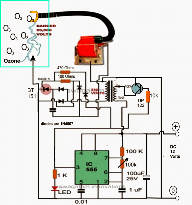
The following diagram illustrates how a CDI circuit may be used as a ozone generator for sterilizing water, air, food etc.
The lower 555 IC circuit is used for triggering TR2 which is an ordinary step down iron core transformer. It's primary is oscillated at its rated voltage through a frequency set by the 100k pot.
This results in the induction of 220V or whatever may the rating of the secondary high voltage winding of the transformer.
Using a Capacitive Discharge Circuit
This induced 220V is fed to the following CDI or the capacitive discharge ignition stage consisting the scr and the ignition coil as the main components.
The SCR along with the high voltage capacitor and the associated diodes fire at the given frequency forcing the 105/400V capacitor to charge/discharge rapidly, dumping the stored 220V at the same rate into the ignition coil primary.
The result is the generation of around 20,000 volts at the secondary high tension output of the ignition coil.
This output is appropriately terminated close to another terminal derived from the negative of the supply.
Once the above set up is configured, the arcing initiates instantly causing the ozone to be generated around the spark zone.
Since excess generation of the ozone could be harmful for the living beings in the premise, the circuit could be triggered through a programmable timer such that it stays switched ON only for some predetermined period of time and gets switched OFF automatically once the set time elapses.
This would ensure the safe amount of ozone to be produced in the premise.
The arcing may be introduced inside any chamber wherein the intended materials or ingredients may be placed and the unit switched ON for initiating the sterilizing actions through the generated ozone gas.
Circuit Diagram
Parts List
- Resistors
- 100k 1/4 w - 1
- 10k 1/4 w - 1
- 1k 1/4 w - 1
- 470 ohms 1/2 w - 1
- 100 ohms 1/2 w - 1
- Capacitors
- 1uF/25V electrolytic - 1
- 100uF/25V electrolytic - 1
- 10nF ceramic disc - 1
- 105/400V PPC - 1
- Semiconductors
- 1N4007 - 4nos
- IC 555 - 1
- TIP122 transistor - 1
- SCR BT151 - 1
- RED LED 5mm 20mA - 1
- Miscellaneous
- Transformer 12-0-12v/1 amp /220V - 1
- Ignition coil 2 wheeler - 1

Comments
Hello , I like a lot your circuits, what is the ideal voltage for the spark or distance to jump, I actually use a 120V circuit that uses a dimmer for lights in series a 1 mF capacitor with motorcycle spark plugs coil and works quite well, also can be regulated with the potentiometer the dimmer has.
Hi, Thanks very much, and Glad you found my circuits helpful.
According to me it requires at least 15000 volts to make a spark jump across a 1 mm distance.
Your dimmer control idea sounds very nice.
Hi, whats the yellow thing on end of cdi please?
Hi, that’s a metal lug at the end of the high tension wire, used for clipping the end to the spark plug.
I understand it is solved
Hello, the red body is in the same shape as the spark transformer, so what is the other transformer? It is near the spark inside the circuit
Other transformer is a standard step-down 0-12 / 220V 1 amp or 500 mA transformer. Red transformer is the ignition coil….
Hey swagatam, how do you drop the 20kv to 3kv?
You can probably do it by supplying around 4.5V DC to the circuit instead of 12V
Hello.
By the way the speed master has a spark duration of 225us which is 4464 Hz so it seems it can handle any feq up to that point set by 555.
Thanks again.
You may be correct!
Hello Swagatam,
In the above circuit a speed master 60,000 volt ignition coil can be had for $28,00 on line. i am curious as to why 230 volts are being pumped into the 12 volt ignition coil when it seems to me a a 1 to 1 isolation coil would work. please explain usage.
Thank you
Hello Donald, the ignition coil costs just a few $ in India.
The input voltage actually can be anywhere between 100 and 220V. This is as per the alternator output voltage found in Indian two wheeler and 3 wheeler vehicles.
The ratio of the primary and secondary is bot 1:1, it is higher than 1:100, and that is why it is able to step up 200 V to 20000 V
Thank you.
03 circuitry.
Hi,
When it’s dipped in water as the HV is @ 20kv does it not give any shock if we touch the water ?
Hi, it is not supposed to be dipped in the water. The sparks should be allowed to work somewhere in the upper dry area of the container, and it must be slowly filled with water so that the running water gets maximum exposure to the generated ozone inside the container.
Hi Swagatam,
FYI. An open arc can generate heat above 2500°F thus forming nitrates in the process.
Lowering the high voltage (below 2500°F) so that a cooler plasma is generated will produce ozone without the nasty nitrates.
Setting up two parallel plates (one for the ground and one for the HV) and adjusting the HV until you see a dull blue glow between them (no arcing) will produce copious amounts of ozone without the nitrates being formed.
Cheers!
Thanks Mike for the wonderful advice! That could be probably done by reducing the input 12V to some suitable lower values…
Hi there, could you please tell me about the capacitor … what´s its rate, how many uF or nF ?
Thanks a lot
The capacitor under the SCR is 105/400V or 1uF/400V PPC
seeing the output is 20kV. it will immerse into water?
using it to wash veg and etc?
Sorry I am new to ion and ozone
actually I am searching for a circuit that to ionizer water and embed it into an instant water heater. Assuming neg – water could neutralize virus in the simple process of in and out (ionized) water
the 20kv will not immerse in water, only the light from the strobe has to pass through water.
I have heard of people turning microwave ovens into welders. Could an old microwave be used to build a Ozone sterilizer unit, if so could you show how? Maybe a youtube video , or even here.
yes that’s possible, however I do not have the details of the design with me at this moment. Perhaps an online search might help you to get the details quickly
https://imgur.com/zG0a00s
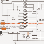
Dear Sir, I am making an air disinfection Ozone transmitter, vegetables, I seem to have the circuit of an ozone generator as shown in the attached image, but I don’t know which IC used in this circuit. I doubt it is NE555 IC as the circuit you have shown above but unfortunately it is not.
Can you help me know what IC name it is? I only know its 3 pin information like it, please help me.
Thank you!
My circuit looks like this product: https://www.greentechenv.com/purifiers/index.php/products/pure-air/pureair-fridge.html
Hi Tanaka,
I am sorry I am unable to identify the IC, yes it’s certainly not IC 555.
However if you are trying to build a smaller version of an ozone purifier you can easily do so by modifying a mosquito bat circuit. You can integrate an external pulsing circuit to produce a 1 second or 2 second arcing, and this will be enough to generate the required amount of ozone inside the refrigerator.
Thank you very much, I will do it and if there are results I will share it here.
You are welcome!!
thanks sir,
I will try to implement it and share the results, but first I also want to learn about the creation of ozone. Do you have any documents about it or your product, can you share it with me.
Sure Tanka. Actually ozone can be created simply by creating a high voltage arc. Thunder lightening, welding sparks, mosquito bat spark all of these effectively generate ozone. I have explained it in the above article, you can read more about it here:
https://en.wikipedia.org/wiki/Ozone
https://imgur.com/pHehuVT
About the circuit I am asking you, I found that it only has a timer function for 30 minutes to power the ozone generator chamber and then turn off, the ozone generation is done from a available generator chamber, besides the circuit has additional anti-plug warning functions. reverse. So I guess it’s an IC timer, so do you know it?
Identifying the specific IC can be difficult, but you can make and customize a different 30 minute timer using an IC 4060, as shown here:
https://www.homemade-circuits.com/simple-adjustable-industrial-timer/
Hello Swagatam,
Thank you very much for giving your valuable time in answering our questions.
Need one more help please can you design Negative ion generator circuit with the input should DC not AC.
Thanks and Regards.
Taibani Imran.
Hello Imran, I have a one circuit which will generate negative ion but with a low current, here's the link:
https://www.homemade-circuits.com/2012/08/make-room-air-ionizer-circuit-get.html
such circuits will generally not work with DC, the DC will first need to converted to AC then applied to the circuit, as shown here
https://www.homemade-circuits.com/2013/05/make-this-car-air-ionizer-circuit.html
Hello Swagatam.
Nice project, I need your help for making this more powerful.
Like if CDI is generating 20kv. How it can generate 50kv.
Can you guide me please.
Thanks and regards.
Taibani Imran.
Hello Imran, I think you can try replacing the shown motorcycle ignition coil with a car ignition coil and see the difference, because a car ignition coil would be much powerful than a motorcycle coil and produce stronger pulses.
sir what are the IC used in circuit for a 30 gm ozonator
Thanks Swagatam ! I have another question, can you send me the link of the detailed schematic diagram ? i cant find it here in your site. thanks !
Ryan, the detailed schematic is already shown in the above article, please click on the diagram to enlarge it.
Good day swagatam ! I have a question how should i implement it to sterilize a water ? should i put the output directly to the water ? thanks for this.
Thanks Ryan, just bring the high tension wire end near the ground wire through a needle arrangement such that these are held 1 inch apart or at a distance where arcing or sparking just initiates and is sustained.
this arcing terminals can be enclosed inside a water tank permanently for executing the sterilizing action, the water may be kept in a cycling motion through a motor propeller mechanism for enabling an effective contact with the generated ozone atmosphere inside the container
Dear Swagatam,
2 questions more sorry..
All transformers (for buy) are AC/AC right?
And how many volts should be in the part of 230 Volt of the transformer? like 230volts?
Thank you
Dear Victor,
TR2 is an ordinary step down transformer with rating: 0-12V/1amp/220V
the red one could be any standard automobile ignition coil…
Dear Swagatam,
This circuit can give High voltage with low frequency (between 50hz and 2000hz)?
Thank you
the capacitor is 105/400V or 1uF/400V metalized polyester type.
the transformer could be a 0-12V/1amp
Thank you for your quick response,
Which is the capacity of the condenser near the diodes?
And which amperage is recommended to have the 230v transformer?
I will try it and let you know, thank you
Dear Victor,
yes, it has to be at lower frequency only, higher frequencies will heat up the ignition coil…
Please sir, i have a question about the Op-amp. My question is: If an op-amp is fed with a supply voltage of 9v for instance, can you generate more than that 9v at the output assuming the gain is properly defined? In simple words, can you generate 15v from 5v input in an Op-amp that is powered with a supply voltage of 12v? If yes, will the output current be significant?
Nope, that's never possible.