This simple two IC circuit can be used for capturing and listening to frequencies in the GHz range.
Receivers designed to cover frequencies as high as several gigahertz (which is many thousand MHz!) are generally difficult to find, specifically for anyone who is looking for cheap versions of these gadgets.
However, it may be possible to develop a GHz receiver which is effective at tuning this kind of high frequencies ranges easily and at low cost.
What is Super High frequency
Super high frequency (SHF) is the ITU certification for radio frequencies (RF) which come in the range of 3 and 30 gigahertz (GHz). This specific band of frequencies is usually called the centimetre band or centimetre wave since their frequencies include wavelengths in the range from one to ten centimetres.
The SHF range of frequency is applied for almost all radar transmitters, wireless LANs, satellite transmission, microwave radio relay links, and various short range terrestrial data links.
Construction Hints
Even when you might have never constructed an electronic circuit earlier, this specific venture should simply present no significant problem to you.
The components could be procured from any online source, or a retail spare parts store near your home.
Even there isn't a need to solder while building the circuit, either a solderless circuit breadboard (for example the versions obtainable from Radio Shack, Vishay, Mouser, Jameco, etc. can be used just as good. That said, soldering the parts over a small veroboard is always the recommended way of building any electronic prototype.
The important thing to keep in mind is to maintain all interconnecting hook up wires across the different components as tiny as possible.
Circuit Description
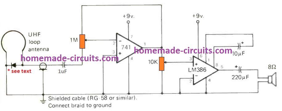
The working of the GHz receiver circuit is simple, the detected signals are captured by the loop antenna. The detector diode demodulates and extracts the audio content from the high frequency carrier waves. The extracted audio signals are fed to the non-inverting input of the IC 741 amplifier circuit. Since its inverting input is grounded, any signal in few mV is enough for the op amp to amplify it to higher levels. The amplified SHF audio signals are applied to a high gain LM386 audio amplifier circuit which finally converts the received GHz range signals into audible sound frequency.
All resistors can be 1/4 -watt types, the tolerance is not really important. The two ICs are normal types, the 741 and LM386.
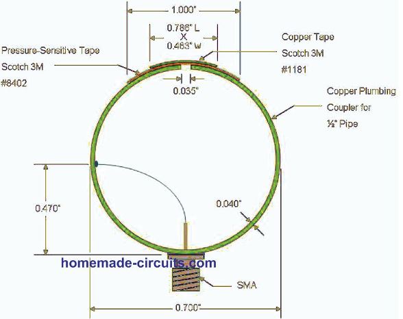
About the Antenna and Reception
The loop antenna could be a UHF loop antenna (the one which plugs in instantly to the UHF sockets on the backside of a television) .
For most effective final results, test out a number of different varieties of diodes. Some of those you can try are 1N21, 1N34, 1N54, and 1N78.
As you could envision, this straightforward circuit comes with its own downsides. The fundamental one is that there is absolutely no way for you to figure out the frequency of a signal you may receive.
Additionally, it is pretty much entirely non-selective.
Probably the most strong signal within the detecting range may simply "overwhelm" the receiver.
Nevertheless, the suggested loop antenna is to some degree directional and may help you to reduce many interfering channels, so that you focus on a specific GHz channel of your choice.
Listening to Satellite and Radar Communication
You may think, what exactly is there to listen to over 1000 MHz? The answer is, different types of radar transmitter signals from ships and airplanes would be the most typical channels, together with radio direction finders, beacons, data and telemetry broadcasts to and from satellites, and HAM radio enthusiasts.
It might be most probably that several different transmission devices unidentified to the DXing community could also be functioning in the specified range of frequency and could hit your receiver speakers.
Why not try your odds at constructing this circuit to check out? Wish you a great snooping in the GHz frequency range, and make sure to review the outcome of your listening to these confidential communications and report them here with your comments.


Comments
Can we use this circuit as UHF based wireless microphone receiver?
I think it can be used…
Thanks a lot
Dear Mr. Swagatam
Hi,Thank you for your good answers. Yes, the first electronic circuit I built was a crystal radio, a very joyful experience. What I meant by the previous content was not that this receiver does not work, it certainly works due to the basic principles of electronics and experiments. What I meant was the need for the circuit to have initial amplification and more accurate filtering. The multiplicity of modulations and frequencies must be considered. AnywayThank you for your efforts and commitment to responding to members. Thank you
Thank you Dear Amirsaraf for your valuable insights, I appreciate it very much!
Dear Swagatam
Hi
Thank you for your reply. As you know, decoupling is extracting the message from the modulated wave, but it does not mean changing the carrier frequency, the diode reduces the frequency by half and gives the message frequency to 741, which undoubtedly contains a large amount of carrier frequency, effectively disabling the IC, the circuit requires careful filtering and low-volume manufacturing
Thank you Dear Amirsaraf, I appreciate your insights, and your understanding is correct.
However, the above design is just a crude form of receiver, quite like a crystal receiver.
You must have read how crystal radio sets work, they only have a coil, and a diode for receiving the nearby radio signals and yet they are able to provide a clear audio output to the headphones.
https://www.homemade-circuits.com/simple-crystal-radio-circuit-using-no/
So the above concept works on a similar principle, where the diode extracts the audio signals from the carrier waves and the 741 preamplifies only these low frequency audio signals for the LM386, for further amplification.
Dear Swagatam
,hi
it doesn’t seem like the 741 IC can work in the SHF band. The circuit must be made with high frequency transistors and as you mentioned, the circuit must be very compact. Thank you
Dear Amirsaraf,
Here the Ic 741 is not detecting or processing the SHF band signals, this is being done by the detector diode.
The IC 741 is only amplifying the tiny millivolts audio signals demodulated by the detector diode.
What kind of diode should be used in this circuit? I could not find one, that is suitable for such frequencies.
you can use any crystal diode such as OA79 etc
Hi Swagatam!
Thank you for this circuit. Since I am away from home currently I do not have access to tools. Your antenna would need soldering. Would this one work instead?:
https://www.amazon.com/TWAYRDIO-Band-Stubby-Dual-Loop-Antenna-Connector/dp/B09PYCRQ1R
Do you ever sell your circuits built and complete?
Thanks,
Larry
Thank you Larry,
Yes, making the loop antenna as per the given diagram may require special tools and soldering.
Since i am not an audio expert, I am not so sure whether the linked device would work satisfactorily or not.
However, I guess it should work because the antenna is not very critical in the above concept.
So, if you are ready to invest $22 for experimenting with this antenna, you can surely go for it.
Nowadays I do not build and sell electronic kits.
Hi Swagatam:
Thanks so much for your speedy reply. I truly appreciate it!
Larry
You are welcome Larry!
can use two ne5534’s instead of 741 and lm386 ??
I don’t think that would work!!
The dimensions of the loop antenna must be questioned.
The outside diameter is 0.7inch but there is a 1inch dimension at the top which makes it wrong.
According to the book “Radio and Electronics Cookbook” which contains a UHF Field Strength Meter, a Loop for 432MHZ is 190mm diameter=7.48 inches (600mm length of wire is required ).
I love the design which I am going to build.
I am trying to use 433Mhz radio TX – RX but looking at your circuit it would be nice to hear the signal produced by my radio is there a circuit that you know that would listen to 433Mhz radio
Thanks, Bob
You can probably modify the Rx module itself by adding a small audio amplifier at one of its output pins, this will allow you to reproduce any audio signal applied to the transmitter’s relevant pin, or you can also modify an existing FM radio by changing the number of turns of its main tuning inductor or the the capacitors involved near the LC tank area.