In this post I have explained a simple plug-in type night lamp circuit with delayed switch OFF and dimming facilities. The entire circuit is built using a transformerless power supply which ensures that the unit is very compact and can be plugged into any existing 220V mains AC socket.
Circuit Description
The electronic schematic of the LED night lamp is shown in the figure below. For once, we will start studying the schema from the end by noting that 4 high-brightness white LEDs are arranged in series and powered by the low-power transistor T1.
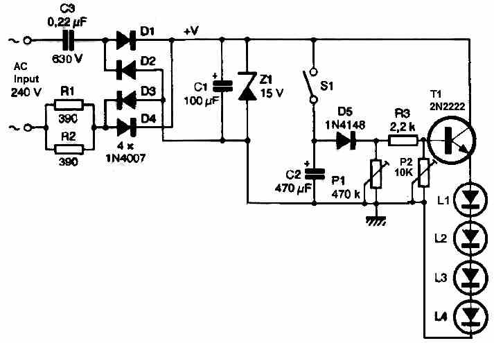
It is clear that a voltage of 4 x 3.6 volts is required, and with the voltage drop of 0.6 volts of the transistor, the 15-volt power supply voltage in the schema is easily justified.
We did not use the classic transformer schema but instead used the capacitive impedance of a non-polarized capacitor. The impedance of the capacitor is calculated using the following formula:
Z = 1 / Cω = 1 / C.2.π.f
To obtain the necessary 20 milliamperes, a value of 0.22 pF will be sufficient. It will also be necessary to ensure that a component with sufficient insulation voltage is chosen to prevent any risk of breakdown or premature aging. A minimum voltage of 630 volts is recommended.
Diodes D1 to D4 (1A/1000 volts models) form a classic double alternate Graetz bridge, whose rectified voltage produced is filtered by the electrolytic capacitor C1 and stabilized at 15 volts by the Zener diode Z1.
To have a constant lighting, it would be sufficient to permanently control the base of the transistor through the resistor R3.
Soft Delayed Switch OFF
A press on the ON/OFF switch S1 turns on the 4 LEDs, but at the same time charges the capacitor C2, a real energy reserve, which will discharge through the adjustable P1, acting here as a real delay adjustment of the LED lighting time (delayed slow switch OFF).
Dimming Facility
Pot P2 enables the brightness adjustment, and this pot can be used to adjust the brightness of the LEDs. Thus P2 acts like a dimmer control on the LEDs.
For more power and illumination, you can add a couple of more LEDs in series to make the total number of LEDs 6.
Construction
We propose a small PCB design for this simple LED night lamp circuit, as shown below. The PCB groups all the components and is perfectly adapted to fit in the bottom of a small plastic, waterproof enclosure.
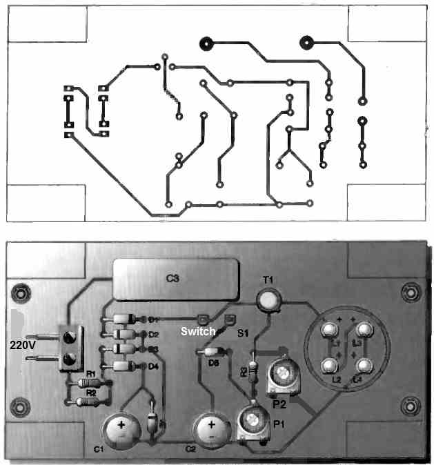
It has a gasket under its transparent Makrolon cover. It remains to make the push button and the power cable outlet waterproof with a suitable silicone sealant for outdoor use.
Regarding the ON/OFF button, it can be replaced by any mechanical or automatic control device. This unpretentious lighting device will find its place in your environment for minimal power consumption and exceptional longevity.
Warning: Since a capacitive power supply is used for the above circuit, the entire circuit is not isolated from AC mains. Therefore, the entire PCB board may be floating with dangerous AC mains potential. Do not touch the circuit while it is switched ON and in an uncovered position.


Comments
Hello, good afternoon, Mr Swagatam. I am contacting you to ask for your help. I would like to manufacture or modify a standard dimmer switch to make it automatic. In other words, when I turn on the light (e.g. Philips LED E27 lamp) in the dining room, it turns on at 100% intensity. However, after a few hours, the light intensity begins to decrease to 5% or 10%, like a night light, and remains that way until I turn the switch back on. Thank you very much in advance.
Hello Mr. Carlos, First I would like you to do the following experiment and check if it works or not. Please connect a 0.47uF/400V PPC capacitor in series with an LED lamp wire and check if its illumination becomes less or not. If it does, then we can proceed next and add a delay timer to switch ON this series capacitor after maybe a few hours, as required by you…