In this post we are going to interface SD card module with arduino for data logging. We will see overview of SD card module and understand its pin configurations and on board components. Finally we will be constructing a circuit to log the temperature and humidity data to SD card.
Secure Digital Card
SD card or Secure Digital card is boon for modern electronics as it provides high capacity storage at minimal size. We have used the SD card for media storage in one of the previous project (Mp3 player). Here we are going to use it for data logging.
Data logging is the fundamental step to record the past occurrence of an incident. For example: scientists and researchers able to interpret the rise of global temperature.
They came to this conclusion after understanding the rising temperature pattern by looking the data of past few decades. Recording the data about the current incident might also disclose about the future occurrence.
Since arduino being a great microcontroller for reading sensor data and supports various communication protocols to read the sensors and input output peripherals, the connection between SD card module arduino made piece of cake.
Since arduino don’t have any storage other than its own program storage space, we can add an external storage using the described module in this article.
Now let’s take a look at SD card module.
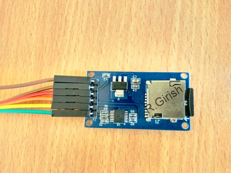
Image of SD card module:
Flipside of the module and pin configuration:
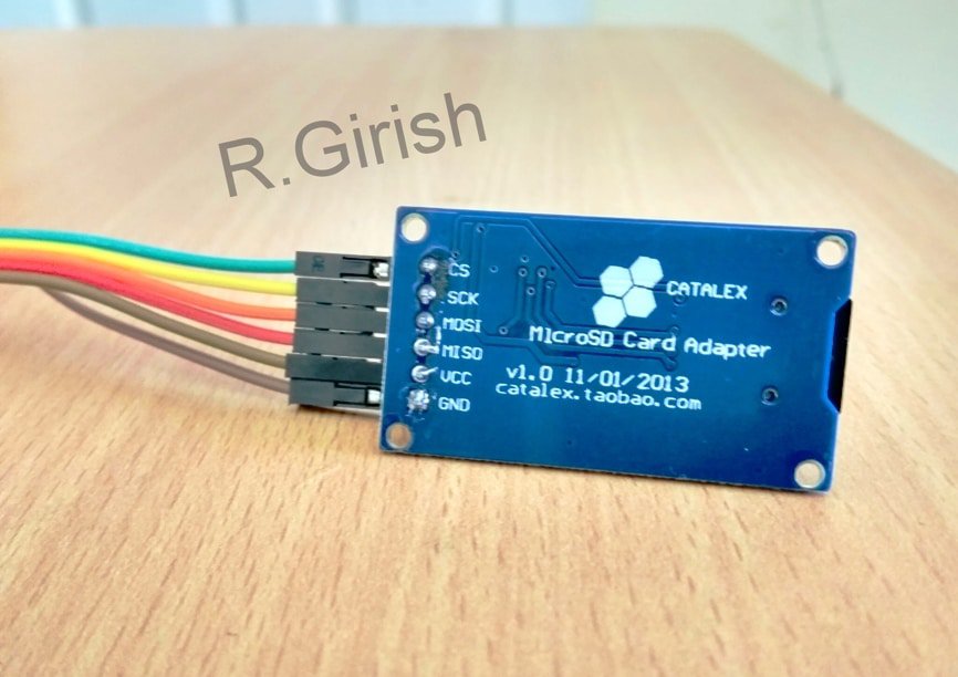
There are six pins and it supports SPI (serial peripheral interface) communication protocol. For Arduino UNO the SPI communication pins are 13, 12, 11, and 10. For Arduino mega the SPI pins are 50, 51, 52 and 53.
The proposed project is illustrated with Arduino UNO if you have any other model of Arduino please refer internet for the SPI pins.
The module consists of a card holder which holds the SD card in place. 3.3V regulator is provided to limit the voltage to SD cards as it is designed to function at 3.3V and not 5V.
It has LVC125A integrated circuit on board which is logic level shifter. The function of logic level shifter is to reduce 5V signals from arduino to 3.3V logic signals.
Now that concludes the SD card module.
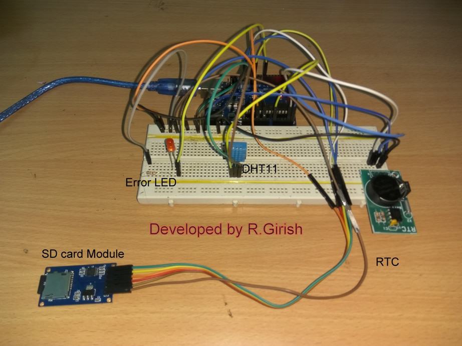
Using SD card module we can store any king of data, here we are going to store text data. We will be storing temperature and humidity data to SD card. We are also utilizing real time clock module to log the time along with sensor data. It records the data every 30 seconds.
Schematic diagram:
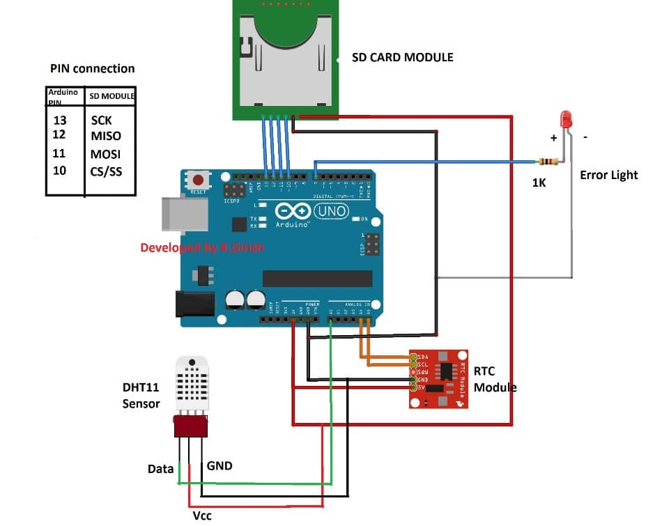
The RTC module will keep track of time and log the date and time to the SD card.
The error LED blinks rapidly, if the SD card fails or fails to initialize or SD card not present. Rest of the time the LED stay off.
HOW TO SET TIME TO RTC:
• Download the library below.
• With completed hardware setup, connect the arduino to PC.
• Open arduino IDE
• Go to File> Examples>DS1307RTC> SetTime.
• Upload the code and RTC will get synchronised with computer’s time.
• Now upload the code given below.
Please download following arduino library before uploading the code.
DS1307RTC: github.com/PaulStoffregen/DS1307RTC
DHT11 temp & humidity: arduino-info.wikispaces.com/file/detail/DHT-lib.zip
Program:
//-----Program developed by R.Girish-----//

#include <SPI.h>

#include <SD.h>

#include <Wire.h>

#include <TimeLib.h>

#include <DS1307RTC.h>

#include <dht.h>

#define DHTxxPIN A0

const int cs = 10;

const int LED = 7;

dht DHT;

int ack;

int f;

File myFile;

void setup()

{

Serial.begin(9600);

pinMode(LED,OUTPUT);

if (!SD.begin(cs))

{

Serial.println("Card failed, or not present");

while(true)

{

digitalWrite(LED, HIGH);

delay(100);

digitalWrite(LED, LOW);

delay(100);

}

}

Serial.println("Initialization done");

}

void loop()

{

myFile = SD.open("TEST.txt", FILE_WRITE);

if(myFile)

{

Serial.println("----------------------------------------------");

myFile.println("----------------------------------------------");

tmElements_t tm;

if(!RTC.read(tm))

{

goto A;

}

if (RTC.read(tm))

{

Serial.print("TIME:");

if(tm.Hour>12) //24Hrs to 12 Hrs conversion//

{

if(tm.Hour==13)

{

Serial.print("01");

myFile.print("01");

Serial.print(":");

myFile.print(":");

}

if(tm.Hour==14)

{

Serial.print("02");

myFile.print("02");

Serial.print(":");

myFile.print(":");

}

if(tm.Hour==15)

{

Serial.print("03");

myFile.print("03");

Serial.print(":");

myFile.print(":");

}

if(tm.Hour==16)

{

Serial.print("04");

myFile.print("04");

Serial.print(":");

myFile.print(":");

}

if(tm.Hour==17)

{

Serial.print("05");

myFile.print("05");

Serial.print(":");

myFile.print(":");

}

if(tm.Hour==18)

{

Serial.print("06");

myFile.print("06");

Serial.print(":");

myFile.print(":");

}

if(tm.Hour==19)

{

Serial.print("07");

myFile.print("07");

Serial.print(":");

myFile.print(":");

}

if(tm.Hour==20)

{

Serial.print("08");

myFile.print("08");

Serial.print(":");

myFile.print(":");

}

if(tm.Hour==21)

{

Serial.print("09");

myFile.print("09");

Serial.print(":");

myFile.print(":");

}

if(tm.Hour==22)

{

Serial.print("10");

myFile.print("10");

Serial.print(":");

myFile.print(":");

}

if(tm.Hour==23)

{

Serial.print("11");

myFile.print("11");

Serial.print(":");

myFile.print(":");

}

else

{

Serial.print(tm.Hour);

myFile.print(tm.Hour);

Serial.print(":");

myFile.print(":");

}

Serial.print(tm.Minute);

myFile.print(tm.Minute);

Serial.print(":");

myFile.print(":");

Serial.print(tm.Second);

myFile.print(tm.Second);

if(tm.Hour>=12)

{

Serial.print(" PM");

myFile.print( " PM");

}

if(tm.Hour<12)

{

Serial.print("AM");

myFile.print( " AM");

}

Serial.print(" DATE:");

myFile.print(" DATE:");

Serial.print(tm.Day);

myFile.print(tm.Day);

Serial.print("/");

myFile.print("/");

Serial.print(tm.Month);

myFile.print(tm.Month);

Serial.print("/");

myFile.print("/");

Serial.println(tmYearToCalendar(tm.Year));

myFile.println(tmYearToCalendar(tm.Year));

Serial.println("----------------------------------------------");

myFile.println("----------------------------------------------");

} else {

A:

if (RTC.chipPresent())

{

Serial.print("RTC stopped!!!");

myFile.print("RTC stopped!!!");

Serial.println(" Run SetTime code");

myFile.println(" Run SetTime code");

} else {

Serial.print("RTC Read error!");

myFile.print("RTC Read error!");

Serial.println(" Check circuitry!");

myFile.println(" Check circuitry!");

}

}

ack=0;

int chk = DHT.read11(DHTxxPIN);

switch (chk)

{

case DHTLIB_ERROR_CONNECT:

ack=1;

break;

}

if(ack==0)

{

f=DHT.temperature*1.8+32;

Serial.print("Temperature(C) = ");

myFile.print("Temperature(°C) = ");

Serial.println(DHT.temperature);

myFile.println(DHT.temperature);

Serial.print("Temperature(F) = ");

myFile.print("Temperature(°F) = ");

Serial.print(f);

myFile.print(f);

Serial.print("n");

myFile.println(" ");

Serial.print("Humidity(%) = ");

myFile.print("Humidity(%) = ");

Serial.println(DHT.humidity);

myFile.println(DHT.humidity);

Serial.print("n");

myFile.println(" ");

}

if(ack==1)

{

Serial.println("NO DATA");

myFile.println("NO DATA");

}

for(int i=0; i<30; i++)

{

delay(1000);

}

}

myFile.close();

}

}
//-----Program developed by R.Girish-----//
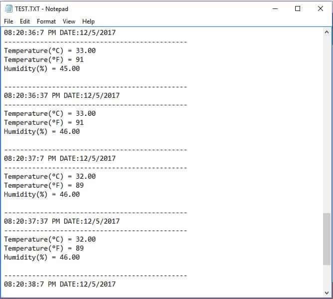
Once the circuit is allowed to log data for some time, you can remove the SD card connect to your computer, there will be TEXT.txt file which all the temperature and humidity data is recorded along with time and date, as shown below.
NOTE: The above idea is an example how to interface and record data. The utilization of this project depend on your imagination, you can record sensor data of any kind.
Author’s prototype:
Need Help? Please Leave a Comment! We value your input—Kindly keep it relevant to the above topic!