In this post we will understand a current controller and current limiter circuit using the IC LM393 comparator. This circuit is using a low power voltage comparator integrated circuit LM393 and one power Metal Oxide Semiconductor Field Effect Transistor, so the idea is simple but the working looks a little deep when we see it first time.
Audio Video Representation
Power supply
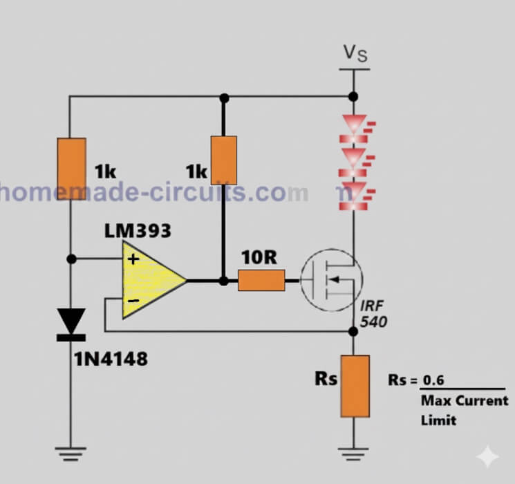
First you look at the power supply line, that is marked as supply voltage, so this supply voltage is directly feeding the load, and in this example the load is shown as a series of light emitting diodes.
Now these light emitting diodes cannot be allowed to take unlimited current, because if current increases too much then they will heat up and get damaged.
So the main job of this LM393 current controller circuit is actually very simple, it keeps watching the load current all the time and the moment the current tries to go above a safe level, then it automatically pushes it down without switching anything off.
Current Sensing Resistor
Now we come to one very important part, that is the sense resistor Rs, which is connected between the source terminal of the Metal Oxide Semiconductor Field Effect Transistor and ground, so this small resistor looks simple but it is doing the main sensing job here.
Whenever current flows through the load, that same current must also pass through this sense resistor Rs, so because of this, a small voltage drop appears across this resistor, now this voltage drop is very important.
More current flowing means more voltage appearing across the sense resistor and less current means less voltage, so this voltage becomes a mirror of the load current.
Now let us move to the voltage comparator integrated circuit, so this integrated circuit is always comparing two voltages side by side, one is a fixed reference voltage and the other one is the sense voltage coming from the sense resistor.
Reference Voltage
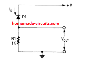
The reference voltage is created using a silicon switching diode connected to ground and this diode gives a nearly fixed voltage of around 0.6 volts, it does not change much so it becomes a stable reference.
This reference voltage is fed to the non inverting input of the comparator and the inverting input is connected to the voltage coming from the sense resistor, so now the comparator is continuously watching both voltages.
As long as the voltage across the sense resistor Rs is lower than the diode reference voltage, the comparator output stays in a condition that allows the Metal Oxide Semiconductor Field Effect Transistor to remain switched on properly, so current flows normally through the load without any restriction.
What Happens during an Over Current Situation
Now see what happens when the load current starts increasing.
As current increases, the voltage across the sense resistor Rs also increases, slowly slowly, and the moment this voltage reaches the same level as the reference voltage, the comparator immediately detects it.
At that exact moment, the comparator output changes its state, and this output is connected to the gate terminal of the Metal Oxide Semiconductor Field Effect Transistor through a resistor.
So when the comparator output changes, it starts reducing the gate voltage of the Metal Oxide Semiconductor Field Effect Transistor, and because of this the transistor begins to reduce its conduction.
As the conduction reduces, the load current automatically comes down, so the circuit is correcting itself without any delay.
Even though a Comparator is used Current Limiting is Smooth, not Abrupt
Now one very important thing to understand here is this, this is not an on and off type action, it is not like a switch cutting power, instead it is a smooth continuous control.
The comparator and the Metal Oxide Semiconductor Field Effect Transistor together form a feedback loop, so if current tries to rise, the transistor conducts less, and if current tries to fall, the transistor conducts a little more.
Because of this continuous feedback action, the current stays locked around the maximum safe value and does not cross it.
Setting the Current Limit Threshold
Now let us understand how this maximum current value is decided.
The rule is very simple here.
The reference voltage from the diode is around 0.6 volts, so the maximum current is equal to 0.6 volts divided by the value of the sense resistor.
Rs = 0.6 / Maximum Current Limit
If the sense resistor Rs is 1 ohm, then the current limit becomes 0.6 ampere.
If the sense resistor is 0.5 ohm, then the current limit becomes 1.2 ampere.
So just by changing the value of the sense resistor Rs, you can accurately set how much current you want the circuit to allow.
Transistor Biasing Resistors, How they Work
Now look at the two resistors connected to the comparator output.
One resistor is used to pull the output toward the supply voltage, and the other resistor is used to limit the gate current going into the Metal Oxide Semiconductor Field Effect Transistor.
These resistors help in keeping the circuit stable and prevent unwanted oscillations or sudden jumps.
Summarizing
This circuit measures current using a resistor. It compares this current related voltage with a fixed reference voltage.
When the current tries to cross the safe limit, the comparator reduces the gate drive. The transistor automatically limits the current. And because of this, the load remains protected all the time.
This type of circuit is very useful in light emitting diode drivers, battery chargers, power supplies, and laboratory current limiters, where current safety is more important than anything else.


Need Help? Please Leave a Comment! We value your input—Kindly keep it relevant to the above topic!