• Skip to main content
  • Skip to primary sidebar

Homemade Circuit Projects

Need circuit help? Post them in the comments! I've answered over 50,000!

Blog | Categories | About | Contact | Calculators-online
You are here: Home / Audio and Amplifier Projects / Simple Intercom Circuit [2 way]

Simple Intercom Circuit [2 way]

Last Updated on January 2, 2024 by Swagatam 12 Comments

The article presented below describes a very simple intercom system which can be built and installed at any required place very cheaply. The circuit utilizes just a single IC and a very few other components for the entire assembly.

How it Works

If you are looking for a simple and low cost intercom system for home installation, you would love the explained project.

The circuit only uses a single chip for the amplification purpose and a couple of speakers along with a handful of passive components for acquiring the intending intercom application circuit.

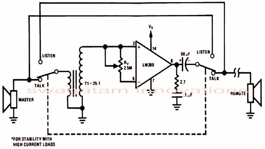
As seen in the figure the entire circuit hovers around the IC LM380 which is another versatile amplifier IC just like it's younger brother IC LM386.

The IC is manufactured by:

national semiconductor 2

However this chip is even better as it requires very few external components for implementing the amplifier actions.

In the diagram we see that the input of the IC is connected to a small loudspeaker via a small output transformer.

The output of the IC is also connected to a loudspeaker.

A DPDT switch is configured and connected to the two speakers such that the whole circuit works like a two way intercom system.

The connected loudspeakers act as a speech producing devices as well as mics for capturing sound signals for amplification to the other end.

The right end speaker is the master while the speaker connected at the other end is for remote installation.

When the switch is positioned toward the talk mode, the master speaker behaves as the mic, and the sound signal is announced and heard over the remote speaker.

When the switch is positioned toward the listen mode, all the conservation that might take place around the remote speaker is transferred and can be heard over the master speaker.

T1 is nothing but a small audio output transformer which may be easily procured from the market, the winding with lower impedance goes to the speaker while the side with the higher impedance gets connected to the input of the IC.

Circuit Diagram

simple intercom circuit using op amp IC LM380

Simple Intercom using Transistors

A simple intercom can be also built using just a couple of transistors as shown below:

transistorized intercom circuit

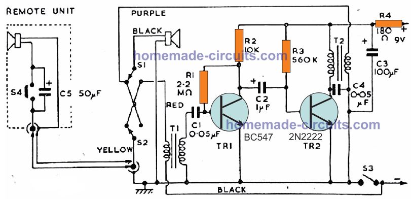
For complete explanation you can refer to this article

You'll also like:

  • 1.  Touch Volume Control Circuit
  • 2.  Audio Delay Line Circuit – For Echo, Reverb Effects
  • 3.  Prevent Amplifier Fuse from Blowing During Power Switch ON
  • 4.  Sound Activated Automatic Amplifier Mute Circuit
  • 5.  SMPS 2 x 50V 350W Circuit for Audio Power Amplifiers
  • 6.  10 Stage Sequential Latch Switch Circuit Diagram

About Swagatam

I am an electronics engineer with over 15 years of hands-on experience. I am passionate about inventing, designing electronic circuits and PCBs, and helping hobbyists bring their projects to life. That is why I founded homemade-circuits.com, a website where I share innovative circuit ideas and tutorials. Have a circuit related question? Leave a comment.... I guarantee a reply!

Previous Post: « LM386 Amplifier Circuit [Working and Application Circuits]
Next Post: Room Air Ionizer Circuit – For Pollution Free Living »

Reader Interactions

Comments

  1. Ugwu, Alphaeus Jideofor says

    April 6, 2025 at 9:37 pm

    I very much commend you for the strength you built up to be producing all these cct. diagrammed.
    (1) I have confusion on how to connect S1 and S2 in a PCB, please fix the two switches physical on the PCB and explain the type of switches they are.
    (2) what type of transformers T1and T2 are.
    (3) connect the remote terminal in the circuit, I do not understand the symbolic way they are now.
    Thank you.

    Reply
    • Swagatam says

      April 7, 2025 at 1:37 pm

      Hi, thanks, I would recommend you to build the first circuit, which looks much cleaner and easier to configure. For the amplifier you can simply replace the LM380 with Lm386 amplifier module.
      The switch is a DPDT type switch.
      The transformer can be any small audio output transformer.

      Reply
  2. Enrico says

    November 13, 2024 at 9:15 pm

    The use of transformers, because of the difficolty to find it easily, greatly reduce the willing to consider the project

    Reply
    • Swagatam says

      November 14, 2024 at 7:51 am

      You can replace the transformer with any suitable BJT preamplifier circuit.

      Reply
  3. John C says

    November 28, 2021 at 2:45 am

    Have you got a simple circuit for using a couple of those basic speaker mics that the 2-way radios use? They’re available pretty cheap, and contain both a speaker and a mic. The push-to-talk switch could be used to turn on the amp?

    Thanks!
    John C

    Reply
    • Swagatam says

      November 28, 2021 at 11:34 am

      I guess you are referring to walkie-talkie circuits, here’s the link where you can find a few of those circuits:

      https://www.homemade-circuits.com/?s=walkie+talkie

      Reply
  4. Zay Yar says

    October 16, 2016 at 3:44 am

    How do i get operation intercom with speaker and this circuit is used tda2003?

    Reply
    • Swagatam says

      October 16, 2016 at 4:05 am

      replace the LM380 stage with TDA2030 stage

      Reply
  5. thecomputerangelcrew says

    January 12, 2016 at 11:30 pm

    wish I could communicate with some nearby buildings wireless, could you help?

    Reply
    • Swagatam says

      January 14, 2016 at 1:44 am

      you can do it by using two FM radios and two small FM transitters, tune these at slightly different stations for communicating across them.

      Reply
  6. Khien Gross says

    November 13, 2014 at 8:40 am

    what is the switch used in the listen and talk? does this have a mic?

    Reply
    • Swagatam says

      November 14, 2014 at 4:38 am

      the speaker works both ways, as a loudspeaker as well as a mic

      Reply

Need Help? Please Leave a Comment! We value your input—Kindly keep it relevant to the above topic! Cancel reply

Your email address will not be published. Required fields are marked *

Primary Sidebar

Subscribe to New Circuit Ideas

Categories

  • Arduino Projects (87)
  • Audio and Amplifier Projects (132)
  • Automation Projects (17)
  • Automobile Electronics (101)
  • Battery Charger Circuits (82)
  • Datasheets and Components (102)
  • Electronics Theory (143)
  • Free Energy (37)
  • Games and Sports Projects (11)
  • Grid and 3-Phase (19)
  • Health related Projects (25)
  • Home Electrical Circuits (12)
  • Indicator Circuits (14)
  • Inverter Circuits (87)
  • Lamps and Lights (142)
  • Meters and Testers (69)
  • Mini Projects (46)
  • Motor Controller (64)
  • Oscillator Circuits (27)
  • Pets and Pests (15)
  • Power Supply Circuits (108)
  • Remote Control Circuits (50)
  • Security and Alarm (64)
  • Sensors and Detectors (100)
  • Solar Controller Circuits (59)
  • Temperature Controllers (42)
  • Timer and Delay Relay (49)
  • Transmitter Circuits (29)
  • Voltage Control and Protection (37)
  • Water Controller (36)

Calculators

  • Battery Back up Time Calculator
  • Capacitance Reactance Calculator
  • IC 555 Astable Calculator
  • IC 555 Monostable Calculator
  • Inductance Calculator
  • LC Resonance Calculator
  • LM317, LM338, LM396 Calculator
  • Ohm’s Law Calculator
  • Phase Angle Phase Shift Calculator
  • Power Factor (PF) Calculator
  • Reactance Calculator
  • Transistor Astable Calculator
  • Transistor base Resistor Calculator
  • Voltage Divider Calculator
  • Wire Current Calculator
  • Zener Diode Calculator
  • Filter Capacitor Calculator
  • Buck Converter Calculator
  • Boost Converter Calculator
  • Solar Panel, Inverter, Battery Calculator
  • Wire Current Calculator
  • SMPS Transformer Calculator
  • IC SG3525, SG3524 Calculator
  • Inverter LC Filter Calculator

People Also Search

555 Circuits | 741 Circuits | LM324 Circuits | LM338 Circuits | 4017 Circuits | Ultrasonic Projects | SMPS Projects | Christmas Projects | MOSFETs | Radio Circuits | Laser Circuits | PIR Projects |

Recent Comments

  • Swagatam on Simple Delay Timer Circuits Explained
  • Swagatam on The Role of Inductor Coil in SMPS
  • Swagatam on 7 Modified Sine Wave Inverter Circuits Explored – 100W to 3kVA
  • Swagatam on 7 Modified Sine Wave Inverter Circuits Explored – 100W to 3kVA
  • Victor on 7 Modified Sine Wave Inverter Circuits Explored – 100W to 3kVA

Company

  • Privacy Policy
  • Cookie Policy
  • About Me
  • Contact
  • Disclaimer
  • Copyright
  • Videos
  • Sitemap

Social Profiles

  • Twitter
  • YouTube
  • Instagram
  • Pinterest
  • My Facebook-Page
  • Quora
  • Stack Exchange
  • Linkedin
  • © 2025 · Swagatam Innovations