In this post, we are going to see how to use an accelerometer with arduino and extract useful readings, which will be printed on serial monitor of IDE. We will also be exploring how accelerometer works in a nutshell and its applications.
How the Accelerometers Works
Accelerometer is an electromechanical device, which is used to detect acceleration. The acceleration can be a static such as gravitational force, while dynamic acceleration can be sudden movement or vibration.
The accelerometer is partially mechanical device because of its internal mechanism. It has moving plates arranged like capacitor, these plates can move freely when it is subjected to external force.
The moving plates are separated few micrometers between them and it is extremely tiny and packed into IC form which is few millimeter in size.
The plates which can move freely have microscopic weight attached to it, which is made from silicon. The microscopic weight absorbs any external impact and applies it to moving plates.
When moving plates are subjected to moments it changes its capacitance, which can be detected by external circuits.
Typical accelerometer module:
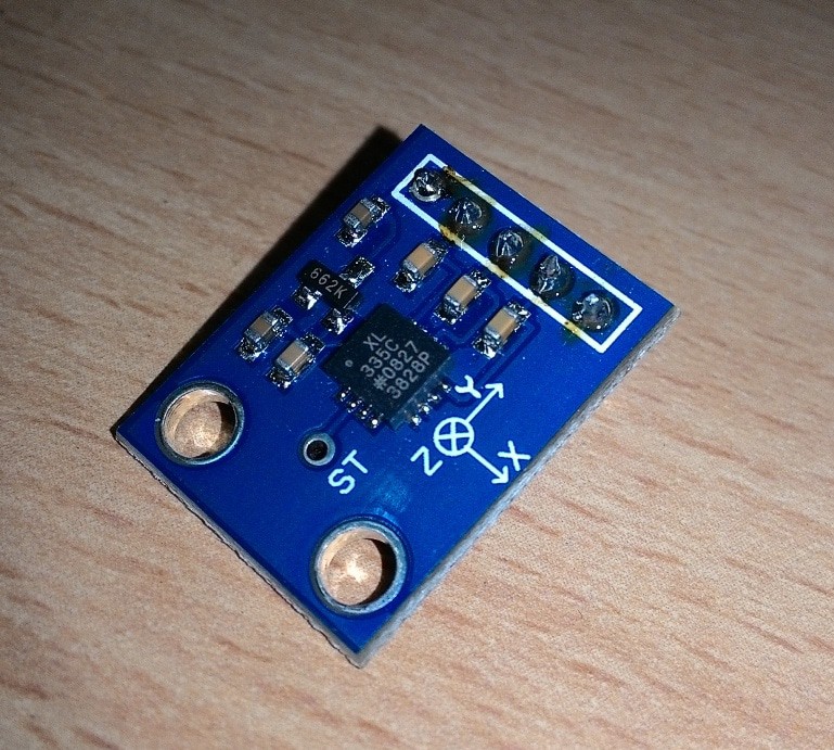
Accelerometer can be single, double or triple axis; here we are using triple axis accelerometer which can detect acceleration in 3 axes i.e. X, Y and Z. This means it has three such moving capacitors placed in X, Y and Z directions fabricated into single IC module.
If you want to know more about accelerometers, you can check out this link which explains how accelerometer works.
The accelerometer used in this project has analogue voltage output with respect to external acceleration. To use it on digital circuits, we need to convert the analogue voltage into digital. The process for converting analogue to digital conversion can be easily accomplished by arduino.
How it Works
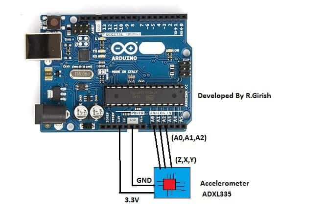
The discussed Arduino accelerometer circuit is very simple as we are only going to extract readings from the accelerometer. The accelerometer has 5 terminals Vcc, GND, X, Y and Z terminals.
The X, Y and Z axes terminals are connected to A2, A1 and A0 terminals of arduino respectively.
The accelerometer can be powered from 3.3V port on arduino. Please take at-most care while powering from external power supplies for projects, 5V can easily damage the accelerometer, it has absolute maximum voltage of 3.6V.
Program Code:
//--------------- Program developed by R. Girish -------------------//
// Improved with comments and minor readability fixes
// No pin changes, no logic changes

// Analog input pins connected to the sensor axes
const int xpin = A2;   // X-axis output connected to A2
const int ypin = A1;   // Y-axis output connected to A1
const int zpin = A0;   // Z-axis output connected to A0

void setup()
{
  // Initialize serial communication at 9600 baud rate
  // Make sure Serial Monitor is also set to 9600
  Serial.begin(9600);
}

void loop()
{
  // Read analog values from each axis
  int xValue = analogRead(xpin);   // Read X-axis
  int yValue = analogRead(ypin);   // Read Y-axis
  int zValue = analogRead(zpin);   // Read Z-axis

  // Print X-axis value
  Serial.print("X=");
  Serial.print(xValue);
  Serial.print("\t");   // Tab space for clean formatting

  // Print Y-axis value
  Serial.print("Y=");
  Serial.print(yValue);
  Serial.print("\t");   // Tab space for clean formatting

  // Print Z-axis value
  Serial.print("Z=");
  Serial.print(zValue);

  // Move to next line after printing all values
  Serial.println();

  // Delay to slow down serial output for readability
  delay(500);
}

//--------------- Program developed by R. Girish -------------------//
The program is very simple; we are assigning three of the analogue pins for input from accelerometer and starting the serial monitor and set its bit rate 9600. Using Serial.print(); we are printing the accelerometer readings on the serial monitor.
OUTPUT:
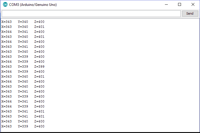
What we can infer from the serial monitor is the voltage level from the accelerometer’s three different axes. When it is subjected external force or tilt it gets reflected in the serial monitor.
We can program the arduino trigger some external peripherals such as relay or LED or motor, when the acceleration or tilt is subject to go beyond pre-determined threshold which we will discuss in the following section.
How to Illuminate an LED with Accelerometer ADXL335 to Detect Acceleration
Here is an Arduino sketch for you to interface with the ADXL335 accelerometer so that you can illuminate an LED whenever a particular acceleration threshold is detected by the ADXL335.
// ---------------- Pin Definitions ----------------
const int xPin = A0;     // X-axis output from ADXL335
const int yPin = A1;     // Y-axis output from ADXL335
const int zPin = A2;     // Z-axis output from ADXL335
const int ledPin = 9;    // LED connected to digital pin 9

// ---------------- ADXL335 Calibration Parameters ----------------
// Sensitivity of ADXL335 = 330mV/g when powered with 3.3V
const float sensitivity = 0.330;   // V/g
const float zeroGVoltage = 1.65;   // Zero-g output voltage at 3.3V supply

// ---------------- Threshold Setting ----------------
// Trigger LED when acceleration magnitude exceeds this value
const float accelerationThreshold = 1.0;   // 1g threshold (adjust if needed)

// ---------------- ADC Reference Voltage ----------------
// Change this if Arduino runs at 5V and sensor at 3.3V
const float adcReferenceVoltage = 3.3;

// ---------------- Helper Function ----------------
// Reads analog voltage and converts it to acceleration in g
float readAcceleration(int pin) {

  int analogValue = analogRead(pin);                 // Read raw ADC value (0–1023)
  float voltage = (analogValue / 1023.0) * adcReferenceVoltage;  // Convert ADC to voltage
  float acceleration = (voltage - zeroGVoltage) / sensitivity;    // Convert voltage to g

  return acceleration;  // Return acceleration in g
}

void setup() {

  pinMode(ledPin, OUTPUT);          // Set LED pin as output
  digitalWrite(ledPin, LOW);        // Keep LED OFF initially

  Serial.begin(9600);               // Serial monitor for debugging

  // Optional: Print startup message
  Serial.println("ADXL335 Acceleration Monitor Started...");
}

void loop() {

  // ---------------- Read Accelerometer Data ----------------
  float xAccel = readAcceleration(xPin);   // X-axis acceleration in g
  float yAccel = readAcceleration(yPin);   // Y-axis acceleration in g
  float zAccel = readAcceleration(zPin);   // Z-axis acceleration in g

  // ---------------- Calculate Vector Magnitude ----------------
  // Magnitude = sqrt(x^2 + y^2 + z^2)
  float magnitude = sqrt(sq(xAccel) + sq(yAccel) + sq(zAccel));

  // ---------------- Threshold Check ----------------
  if (magnitude > accelerationThreshold) {
    digitalWrite(ledPin, HIGH);     // Turn ON LED if vibration/shock detected
  }
  else {
    digitalWrite(ledPin, LOW);      // Turn OFF LED
  }

  // ---------------- Debug Output ----------------
  Serial.print("X: "); Serial.print(xAccel, 3);
  Serial.print("  Y: "); Serial.print(yAccel, 3);
  Serial.print("  Z: "); Serial.print(zAccel, 3);
  Serial.print("  Magnitude: "); Serial.println(magnitude, 3);

  delay(100);   // Sampling delay (reduce for faster response)
}
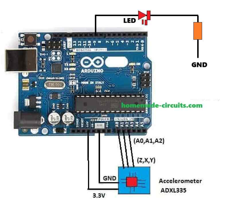
Circuit Diagram
How to Configure the Circuit
ADXL335:
Connect X, Y, and Z outputs to Arduino analog pins A0, A1, and A2 respectively.
Connect VCC to Arduino 3.3V or 5V (as per your ADXL335 breakout board specs).
Connect GND to Arduino GND.
LED:
Connect the anode (the LED long leg) to a digital pin (e.g. D9) via a 220 ohm resistor.
Connect the cathode (the LED short leg) to GND.
How the Circuit Works
When we are talking about sensitivity, we need to tweak both the sensitivity and the zeroGVoltage settings if we’re using a supply voltage that’s different from the standard 3.3V.
For example if we’re using 5V instead, we could set the sensitivity to 0.270 and the zeroGVoltage to 2.5V.
Now we can adjust the accelerationThreshold to pick up on different levels of acceleration.
This means we can fine-tune how sensitive we want our setup to be when it comes to detecting movement.
When it comes to output, if the magnitude of acceleration goes beyond that threshold we set, an LED will light up!
So you can start by uploading this code to our Arduino and then give it a test run by moving the ADXL335 around. Don’t forget that we can always adjust those parameters as needed to fit our specific application!
Applications of accelerometers:
Accelerometer has wide spectrum of applications from smartphone to aircraft.
• The accelerometers are boon for smartphone, have you ever wondered how your screen change its orientation from landscape to portrait and vice versa or the guy in ‘Temple run’ moves left and right when you tilt for phone? Well it’s all the wonder of accelerometer.
• Accelerometer is used in aircraft to measure several parameters to stabilize the fight.
• It is used in digital cameras for optical image stabilization.
• It is used in electronically stabilized tripods for photography professionals.
The above are mere fraction of the application of accelerometer. Now you know what an accelerometer is, how to use with arduino and where it is used.
Verifying the Parameters
ADXL335 Output Range
- The ADXL335 outputs an analog voltage proportional to acceleration. So typically:
- At 0g the output voltage is 1.65V (half the supply voltage if powered by 3.3V).
- The sensitivity is around 330 mV/g when powered by 3.3V or 270 mV/g when powered by 5V.
- Ensure that the breakout board matches the power supply (3.3V or 5V). Update
zeroGVoltageandsensitivityconstants in the sketch if needed.
Analog-to-Digital Conversion
- The Arduino ADC has a 10-bit resolution:
- For 3.3V reference 1 ADC unit = 3.3V / 1023 = 3.225 mV.
- For 5V reference 1 ADC unit = 5V / 1023 = 4.887 mV.
- The conversion from ADC value to voltage in the sketch matches this calculation.
Acceleration Threshold
- The threshold is in units of g (acceleration due to gravity ≈ 9.8 m/s²).
- In the code
accelerationThresholdis set to1.0gbut you can adjust it based on your requirement (e.g. higher thresholds for more robust detection).
Acceleration Magnitude Calculation
- The formula calculates the magnitude of the acceleration vector using:
- Magnitude = x2 + y2 + z2
- This ensures that the LED lights up when total acceleration is detected in any direction.
LED Circuit
- The LED connection is straightforward:
- Use a 220Ω resistor in series with the LED to limit the current.
- Confirm the resistor value matches your LEDs forward voltage and current requirements.
Debugging with Serial Monitor
- The
Serial.printstatements provide real-time readings ofx,y, andzacceleration values as well as the magnitude. This helps you: - To verify if the ADXL335 outputs match expected behavior.
- To ccheck if the calculated acceleration magnitude exceeds the threshold.


Need Help? Please Leave a Comment! We value your input—Kindly keep it relevant to the above topic!