In this post I have explained how to make a high power 100V to 220V H-bridge mains voltage stabilizer circuit using automatic PWM control. The idea was requested by Mr. Sajjad.
Circuit Objectives and Requirements
- I really surprised by your works and intentions to help people, Now allow me to get to my point, I need a voltage regulator with these capabilities as possible 1-focus on low voltage problems rather than high voltages preferably around 100v and up to 250v
- I need high capability of stabilizing and sustaining 3.5 ton air conditioner about 30 amps and other design capable of sustaining 5A for lightening.
- Avoid big transformer as much as possible, I like ferrite transformers
- I found this idea of stabilizer ( https://drive.google.com/file/d/0B5Ct1V0x1 jac19IdzltM3g4N2s/view?usp=sharing ) here is the link I need an schematic with the same idea low input voltage around 100-135v high current to start and sustain 3.5 ton air conditioner and second design for lightening of 6A if you have time
- I want third design with a crazy 100A stabilizer for my whole home I have requested design earlier but I Was having no idea this design looks pretty good to my with elegant efficiency
Secondary Features
I like it to has an LCD to display parameters and a custom name,high voltage cut off, over heat protection but drop it if its makes the design more complex.
I know what I have asked for is way too much to accomplish in one cirute so drop the impossibles to sum up I need three designs one is for high current of air conditioner,two the same regulator but with secondary features mentioned and three one for lightening
you may wonder why its that low 100v input required, most of the time in summer we have no public electricity but we have local generator with electricity of 120-170v at home with our ceiling fan barely rotates
Public electricity is grid electricity which has high current but low voltage with supply time at its best of eight hours a day in summer, on the other hand as I said we have big local generators during this time we pay on the basis of ampers (rated current of the circuit breaker for local electricity) for example say you want 50A they will supply you electricity with circuit breaker of 50A and you have to pay for 50A regardless of your usage (they will assume you are using the whole 50A),
so in my house I pay for grid electricity and local generator electricity, local generator is not my home generator, you can imagine it as a second grid electricity but owned by private sector, in both cases we have voltage problem but not current,
lastly I now that the voltage optimizer in boost mode will use more current to produce the required voltage on the
The principle of conservation of energy (V1xI1=V2xI2) assuming 100% efficiency,the current solution I use now is step up transformer which will reduce the usable current may be to 30A of 50A but with good voltage but it is not safe because of lack regulation,on public electricity we have apparently no limits we pay on the basis of KWh,
Before the transformer I have purchased a voltage regulator but it did not work because the minimum of 180V is not met.
The Design
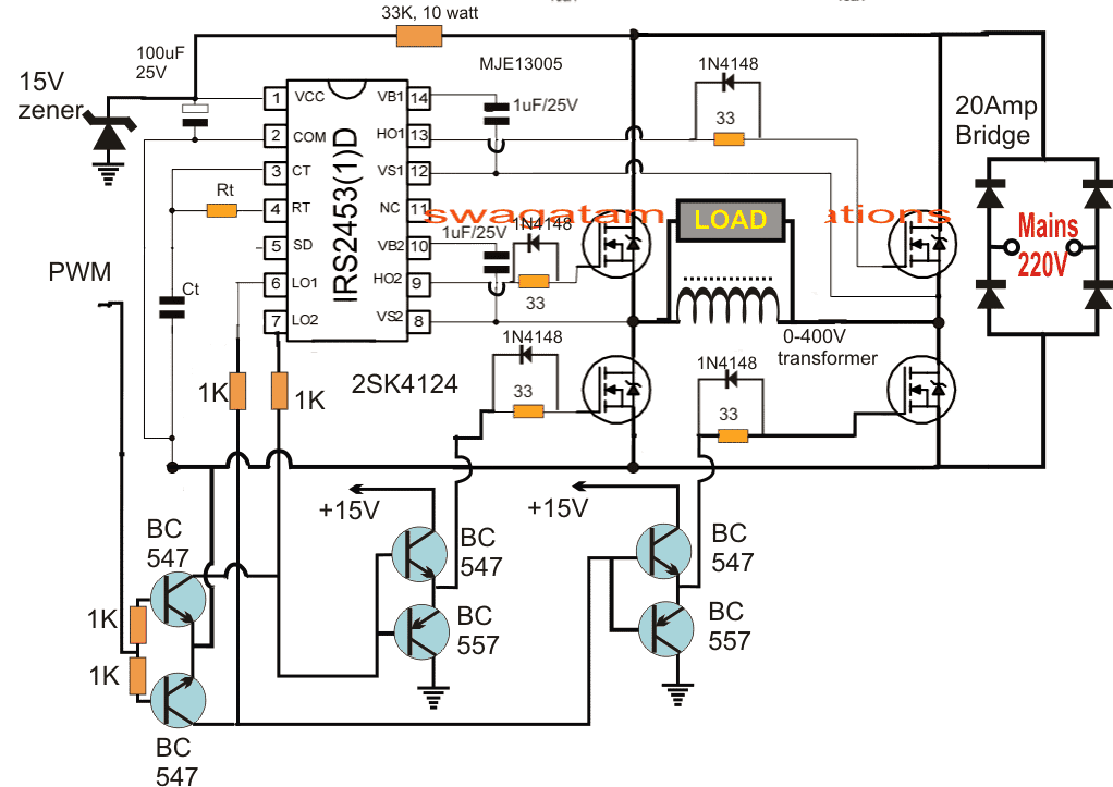
The complete design for the proposed H-bridge mains voltage stabilizer circuit for controlling 100V to 220V can be witnessed in the following figure:
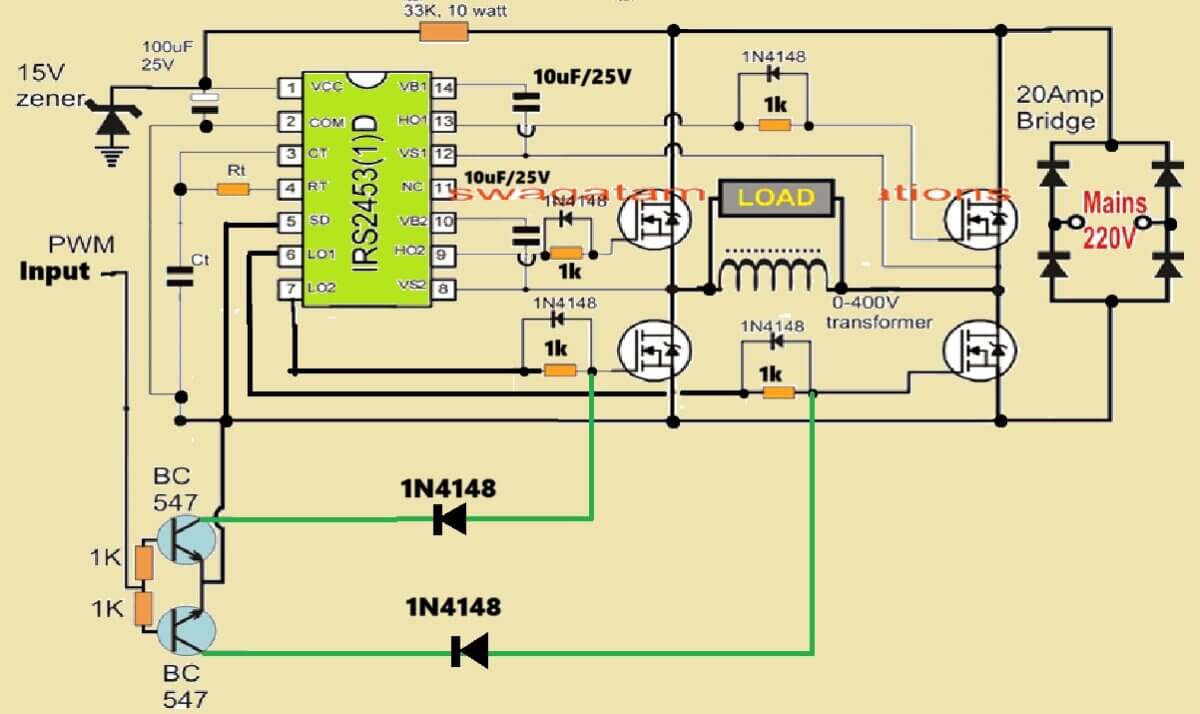
The above design can be much simplified, as given below:
The circuit is functioning is quite similar to one of the earlier discussed posts regarding a solar inverter circuit for a 1.5 ton air conditioner.
However for implementing the intended automatic 100V to 220V stabilization we employ a couple of things here: 1) the 0-400V auto transformer boost coil and the self optimizing PWM circuit.
The above circuit utilizes a full bridge inverter topology using the IC IRS2453 and 4 N-channel mosfets.
The IC is equipped with its own in-built oscillator whose frequency is appropriately set by calculating the indicated Rt, Ct values. This frequency becomes the recommended operating frequency of the inverter which could be 50Hz (for 220V input) or 60Hz (for 120V input) depending on the country utility specs.
The bus voltage is derived by rectifying the input mains voltage and is applied across the H-bridge mosfet network.
The primary load connected between the mosfets is a boost auto-transformer positioned for reacting with the switching mains DC voltage and for generating a proportionately boosted 400V across its terminals through back EMFs.
However with the introduction of a PWM feed for the low side mosfet this 400V from the coil can be controlled proportionately to any desired lower RMS value.
Thus at max PWM width we can expect the voltage to be 400V and at minimum width this could be optimized close to zero.
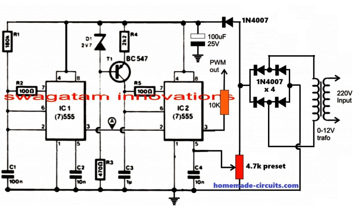
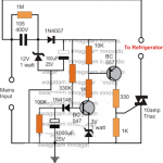
The PWM is configured using a couple of IC 555 for generating a varying PWM in response to the varying mains input, however this response is inverted first before feeding the low side mosfets, which implies that as the mains input drops, the PWMs become wider and vice versa.
To correctly set this response the 1K preset shown attached with pin#5 of the IC2 in the PWM circuit is adjusted such that the voltage across the auto-transformer coil is around 200V when the input is around 100V, at this point the PWM could be at the max width level and from here on the PWMs become narrower as the voltage increases, ensuring an almost constant output at around 220V.
Thus, if the mains input goes higher the PWM tries to pull it down by narrowing the pulses and vice versa.
How to make the Boost Transformer.
A ferrite transformer cannot be used for the above discussed 100V to 220V H-bridge mains voltage stabilizer circuit since the base frequency is adjusted to 50 or 60 Hz, therefore a high grade laminated iron core transformer becomes the ideal choice for the application.
It can be made by winding a single end to end coil of around 400 turns over a laminated EI iron core, using 10 strands of 25 SWG wire...this is an approximate value and is not a calculated data...the user may take the help of a professional auto transformer manufacturer or winder for getting the actual required transformer for a given application need.
In the linked pdf document it is written that its proposed design does not require the AC to DC conversion for the circuit, which looks incorrect and is practically not feasible, because if you are using a ferrite boost transformer inverter then the input AC has to be first converted to DC. This DC is then converted to a high switching frequency for the ferrite transformer whose output is switched back to the specified 50 or 60Hz in order to make it compatible with the appliances.

Comments
Hi I am from Myanmar. I was wondering what would be the better value for Rt, Ct ? If you have time, I need this for my experiment.
Ko San Aye.
Hi, this the formula for calculating Rt Ct
f = 1/1.453 x Rt x Ct
where Rt is in Ohms and Ct in Farads.
Hello . I want to use an igbt transistor instead of a Mosft. Is that possible to get a 15kw power?
Yes it is possible.
Sir,
Quite fascinating by your well illustrated circuit diagrams. But can you illustrate circuit diagrams for ~ 10 – 20 KCA PMW based static voltage stabilizers, as they are having high efficiency and fast responses to voltage variations.
Vikas
Glad you liked it Vikas, I’ll study the concept in detail and if it is feasible for me, will try to post a relevant article soon. thanks for the suggestion.
Pls Mr swag I need a AC voltage measuring circuit.I want the circuit to trigger a relay when it sense a AC voltage above 210v
Hi Joseph, you can try the op amp concept presented in the article
https://www.homemade-circuits.com/how-to-make-small-homemade-automatic/
remove R3 if you want hysteresis
Sir I making circuit again.i give 80v dc convert 80v ac no problems.i use 104×10 in parallel bootstrap capacitor 1uf/25v not available for me can we use 1uf/50v ceramic capacitor or more voltage value
yogesh, you can use 1uF/50V, no problems…
Hello,
it can be calcualted by using Ohm's law:
R = V/I = 275/IC current = 275 / 0.02 = 13750 ohms = around 14K
I have assumed IC current to be 20mA here, although 10mA will also work
Hi Swagatam. Very nice circuit. I have just had a thought. Instead of using the add on circuit for the PWM, why can't you use an Arduino attached to the SD pin of the IRS2453, and use it to monitor output voltage (via a stepdown transformer) and also get it to perform the PWM and feed it into the SD pin. It could be used to produce the sine wave and adjust voltage. What are your thoughts?
Hi, the SD pin is for shutdown implementation..if you apply PWM to this pinout the whole system will start switching or oscillating ON/OFF which cannot be considered as PWM control. the PWM is supposed to control the waveform only and not switch the entire IC ON/OFF
Sir,i use irf840 8A 500v mosfet i give 250v supply and we find 250v output open circuit as we small load apply output voltage only 25v for 50hz we use rt 1.3m and ct 10nf
Yogesh, what is the source of this 220V AC? If the source has the required sufficient amount of current for the load and still the voltage is dropping then your mosfets are not working correctly or there could be some other issue in the circuit…if you are using PWM, remove it and confirm the full bridge section separately first.
Sir I make this circuit again, 1mfd/25v electrolytic capacitor +lead pin 10,14 -lead pin 12,8 and 15vzener pin,pwm section ground joint to bridge negative sir one doubt is transistor T1 symbol is PNP mark 547.for 50hz please accurate rt ct value
Yogesh, 1uF in the first circuit should be non-polar, electrolytic is not recommended.
T1 in the second design is BC557, it's a printing mistake.
RT/CT values can be confirmed using a frequency meter or formula from the datasheet of the IC.
initially any random value, check with frequency meter and then use cross multiplication to get the 50Hz values.
this circuit is absolutely not for the newcomers, please be advised
Rt =1mega ohms or for more accuracy 1.2 mega ohms
Ct 10kpf
you will have to confirm the result through a practical test, I won’t be able to confirm the values.
Sir this circuit is not working proper,pwm work well,drive voltage ok,if 100w load apply no output, if you are design me programable igbt based stabilizer please contact me yogesh8964@gmail.com
Yogesh, Can you please tell me how did you test and optimize the different stages??
The above circuit will work only if it's correctly adjusted and integrated.
It's for the experts who know electronics very well.
I do not have a MCU design at the moment.
Sir can we use irf840 instead 2sk4124 for mall load
Hello sir , in the above diagram the auto transformer “load” seems to serve as regulator , is that right? Or do I still need to march the transformer to the intended load handling capability of the circuit? EG:- if I need 5000w stabilizer, do I need to get a 5000w transformer?
Hello Ugo,
The LOAD is actually the appliance across which the voltage needs to be stabilized. The 0-40V coil watt specifications should match the load specifications or be higher than the load.
Yogesh, please compare their voltage and current handling capacities with the load capacity, then you can decide whether it's appropriate or not.
Sir 1mf/25v electrolytic or ceremic
It can be any type of capacitor….
I am really impressed, thanks a lot.
I will try to make it as soon as possible.
It's my pleasure!! thank you!