In this post I have explained a few simple ESR meter circuits which can be used for identifying bad capacitors in an electronic circuit without removing them practically from the circuit board. The idea was requested by Manual Sofian...
Technical Specifications
Do you have a schematic about ESR meter. Technicians recommend me to check the electrolytic first every time I come up with a dead circuit, But I don't know how to measure it.
Thank you in advance for your answer.
What is ESR
ESR which stands for Equivalent Series Resistance is a negligibly small resistance value that normally becomes a part of all capacitors and inductors and appear in series with their actual unit values, however in electrolytic capacitors especially, due to aging, the ESR value could go on increasing to abnormal levels adversely affecting the overall quality and response of the involved circuit.
The developing ESR in a particular capacitor may gradually increase from as low as a few milliohms to as high as 10 ohms, affecting the circuit response severely.
However the above explained ESR may not necessarily mean that the capacitor's capacitance would also be affected, in fact the capacitance value could remain intact and good, yet have the capacitor's performance deteriorating.
It is due to this scenario a normal capacitance meter entirely fails to detect a bad capacitor affected with high ESR value and a technician finds the capacitors to be OK in terms of its capacitance value which in turn makes troubleshooting extremely difficult.
Where normal capacitance meters and Ohm meters become totally ineffective in measuring or detecting abnormal ESR in faulty capacitors, an ESR meter becomes extremely handy for identifying such misleading devices.
Difference between ESR and Capacitance
Basically speaking, a capacitor's ESR value (in ohms) indicates how good the capacitor is..
The lower the value, the higher the working performance of the capacitor.
An ESR test provides us an quick warning of capacitor malfunction, and is a lot more helpful when compared to a capacitance test.
In fact several defective electrolytics might exhibit OKAY when examined using a standard capacitance meter.
Lately We have spoken to many individuals who don't support the significance of ESR and in exactly what perception it is unique from capacitance.
Therefore I think it is worth providing a clip from a technological news on a reputed magazine authored by Doug Jones, the President of Independence Electronics Inc. He addresses the concern of ESR effectively. "ESR is the active natural resistance of a capacitor against an AC signal.
Higher ESR may lead to time-constant complications, capacitor warming, increase in the circuit loading, overall failure of the system etc.
What Problems can ESR Cause?
A switch-mode power supply with high ESR capacitors may fail to start optimally, or simply not start at all.
A TV screen could be skewed in from the sides/top/bottom due to a high ESR capacitor. It can also lead to premature diode and transistor failures.
All these and many more issues are usually induced by capacitors with proper capacitance but large ESR, that cannot be detected as a static figure and for that reason cannot be measured through a standard capacitance meter or a DC ohmmeter.
ESR shows up only when an alternating current is connected to a capacitor or when a capacitor's dielectric charge is constantly switching states.
This can be viewed as as the capacitor's total in-phase AC resistance, combined with the DC resistance of the capacitor leads, the DC resistance of the interconnection with the capacitor dielectric, the plate resistance of the capacitor and the dielectric material's in-phase AC resistance in a specific frequency and temperature.
All the elements that causes the formation of ESR could be regarded as a resistor in series with a capacitor. This resistor doesn't really exist as a physical entity, hence an immediate measurement over the 'ESR resistor' is just not feasible. If, on the other hand, an approach that helps correcting the results of capacitive reactance is accessible, and contemplating that all resistances are in phase, the ESR could be determined and tested employing the fundamental electronics formula E = I x R!
Simple ESR Meter Circuits using IC 555
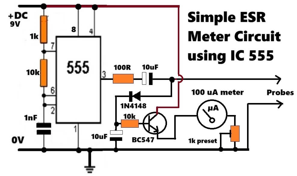
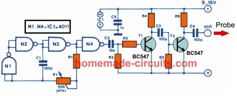
This circuit works in simple way, first NE555 makes high frequency around 70 kHz to 80 kHz using 1k, 10k and 1nF. Here we use high frequency because when frequency increases then Xc = 1 / (2πfC) becomes very small, so capacitor acts almost like short for AC and what remains noticeable is its ESR. That is the trick we implement to read the capacitor ESR.
From pin 3 the square wave goes through 100 ohm and 10µF in series. 100 ohm limits current, 10µF blocks DC. So small AC goes into the capacitor under test. Since voltage is very low then nearby semiconductors usually do not turn on, so in-circuit testing works.
If capacitor is good then ESR is low, so voltage drop across it stays small, meter hardly moves. If ESR is high then bigger drop appears, diode picks it, sends it to filter, meter moves more. So higher ESR means higher deflection.
1N4148 converts AC drop to pulsating DC, 10µF smooths it. Next, DC from across the 10uF goes to BC547 base through 10k. This BC547 transistor then gives current gain, and drives 100µA meter properly for the final ESR reading.
If base voltage rises then emitter current rises, then meter shows higher reading and vice versa... 1k preset in series with the meter is for calibration.
That is all, just high frequency plus small signal sensing of ESR.
How to Calibrate
First short the probes together, so we touch them and then the meter should react.
Now adjust the preset so the meter reads zero...this is important, because if it does not sit at zero then later readings will be wrong, so we trim it slowly and then it comes to zero.
Now connect a known 1Ω resistor across the probes, and if you connect it properly then the needle will move somewhere, so we watch that spot and then we mark that position as 1Ω.
After that connect 2Ω, then 5Ω and when you change each resistor then the pointer shifts again, so we mark those points also, one by one, on the meter dial scale..
We are basically building our own markings, however there is no printed scale for ESR, so we create it manually.
So in the end you get your own ESR scale on the meter, done by manual testing and marking step by step as stated above.
Audio/Video Representation
Another ESR Meter Using IC 555
Not so typical, yet this simple ESR circuit is extremely accurate and easy to build. It employs very ordinary components such as a IC 555, a 5V DC source, an few other passive parts.
The circuit is built using a CMOS IC 555, set with a duty factor of 50:50.
The duty cycle could be altered through the resistor R2 and r.
Even a small change in the value of the r which corresponds to the ESR of the capacitor in question, causes a significant variation in the output frequency of the IC.
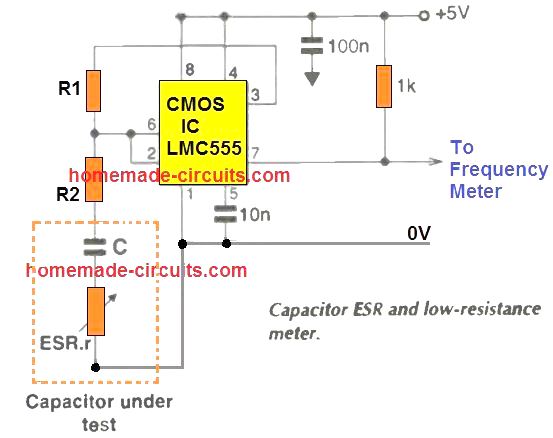
The output frequency is solved by the formula:
f = 1 / 2CR1n(2 - 3k)
In this formula C represents the capacitance, R is formed by (R1 + R2 + r), r denotes the ESR of capacitor C, while the k is positioned as the factor equal to:
k = (R2 + r)/R.
In order to ensure that the circuit works correctly, the factor k value must not be above 0.333.
If it is increased above this value, the IC 555 will go into an uncontrolled oscillating mode, at an extremely high frequency, which will be solely controlled by the propagation delay of the chip.
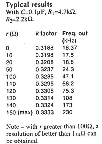
You will find an exponential increase in the output frequency of the IC by 10X, in response to an increase in the factor k from 0 to 0.31.
As it is increased even further from 0.31 to 0.33, cause the output frequency to increase by another 10X magnitude.
Assuming R1 = 4k7, R2 = 2k2, a minimal ESR = 0 for the C, the k factor should be around 0.3188.
Now, suppose we have the ESR value of around 100 ohm, would cause the k value to increase by 3% at 0.3286. This now forces the IC 555 to oscillate with a frequency that's 3 times greater compared to the original frequency at r = ESR = 0.
This shows that as the r(ESR) increases causes an exponential rise in the frequecny of the IC output.
How to Test
First you will need to calibrate the circuit response using a high quality capacitor with negligible ESR, and having a capacitance value identical to the one that needs to be tested.
Also you should have an handful of assorted resistors with accurate values ranging from 1 to 150 ohms.
Now, plot a graph of output frequency vs r for the calibration values,
Next, connect the capacitor which needs to be tested for the ESR, and start analyzing its ESR value by comparing the corresponding IC 555 frequency and the corresponding value in the plotted graph.
To ensure an optimal resolution for lower ESR values, for example below 10 ohms, and also to get rid of frequency disparities, it is recommended to add a resistor between 10 ohm and 100 ohm in series with the capacitor under test.
Also, the power supply used must a very good quality power supply with regulated DC. A 9 V battery with a 7805 IC regulator would be most suitable.
Once the r value is obtained from the graph, you just have subtract the fixed resistor value from this r to get the ESR value.
Yet Another IC 555 ESR Meter Design
The equivalent series resistance (ESR) of a capacitor could be calculated through this circuit and a good ac voltmeter. IC1 works like a 50 kHz square-wave generator.
It pushes a current waveform of approximately ± 180 mA inside the capacitor-under-test, by means of R1 and R2. When pot R3 is tweaked for the correct resistance, the potential drop over the "equivalent series resistor" gets accurately terminated by the inverting amplifier ( IC2). Thus, Vo is the genuine capacitor voltage which is the lowest voltage which is usually created at the output Vo.
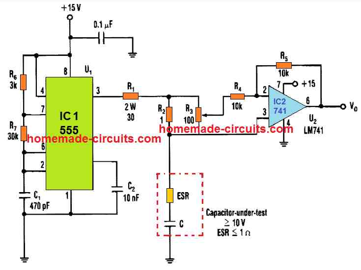
In order to obtain an ac voltage reading, you will have to fine-tune R3 until you find a minimum voltage at Vo output. Next, look at the placement of the potentiometer and multiply it with the value of R2, 10 Ohm in this case.
The multiplied result will be equivalent to the capacitor's ESR. A 7.5 v is used for biasing the capacitor under test, therefore capacitors with lower voltage than this cannot be tested with this ESR meter circuit.
By modifying the R2 value, we can upgrade the circuit for additional ranges of ESR measurement. Having said that, for smaller R2 value the amp level must be higher to enable a fair voltage drop across R2. This might call for some form of intermediate buffer stage.
The circuit will work well for capacitors higher than 100 µF. The ripple voltage will get larger for smaller sized capacitors with a decrease in the accuracy level.
Using an Op Amp for Making a Simple ESR Meter
An ESR meter can be used to determine the health of a doubtful capacitor while troubleshooting an old electronic circuit or unit.
Moreover the good thing about these measuring instruments is that it can be used to measure the ESR of a capacitor without the need of removing or isolating the capacitor from the circuit board making things pretty easy for the user.
The following figure shows a simple ESR meter circuit which can be built and used for the proposed measurements.
Circuit Diagram
How it Works
The circuit may be understood in the following manner:
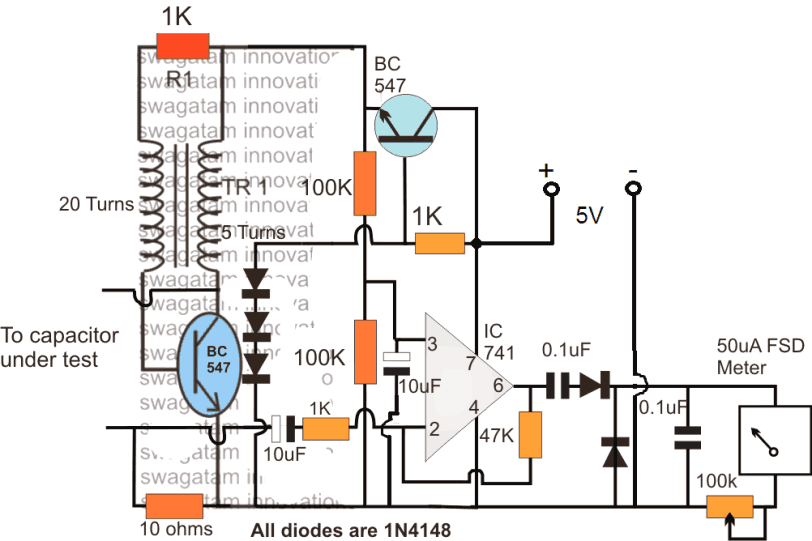
TR1 along with the attached NPN transistor forms a simple feed back triggered blocking oscillator which oscillates at some very high frequency.
The oscillations induce a proportionate magnitude of voltage across the 5 turns secondary of the transformer, and this induced high frequency voltage is applied across the capacitor in question.
An opamp can also be seen attached with the above low voltage high frequency feed and is configured as a current amplifier.
With no ESR or in case of a new good capacitor the meter is set to indicate a full scale deflection indicating a minimum ESR across the capacitor which proportionately comes down toward zero for different capacitors having different amounts of ESR levels.
Lower ESR causes relatively higher current to develop across the inverting sensing input of the opamp which is correspondingly displayed in the meter with a higher degree of deflection and vice versa.
The upper BC547 transistor is introduced as a common collector voltage regulator stage in order to operate the oscillator stage with a lower 1.5 V so that the other electronic device in the circuit board around the capacitor under test is kept under zero stress from the test frequency from the ESR meter.
The calibration process of the meter is easy. Keeping the test leads shorted together the 100k preset near the uA meter is adjusted until a full scale deflection is achieved on the meter dial.
After this, different capacitors with high ESR values could be verified in the meter with correspondingly lower degrees of deflection as explained in the previous section of this article.
The transformer is built over any ferrite ring, using any thin magnet wire with the shown number of turns.
Simple ESR Tester with One LED
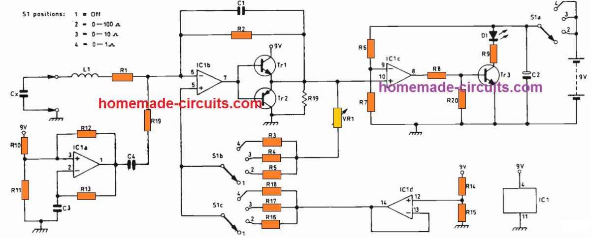
The circuit provides a negative resistance to terminate the capacitor's ESR which is under test, creating a continuous series resonance through a fixed inductor. The figure below exhibits the circuit diagram of the esr meter. The negative resistance is generated by IC 1b: Cx indicates the capacitor under test and L1 is positioned as the fixed inductor.
Basic Working
Pot VR1 facilitates the negative resistance to be tweaked. To test, simply keep turning VR1 until oscillation just stops. Once this is done, the ESR value could be checked from a scale attached behind the VR1 dial.
Circuit Description
In the absence of a negative resistance, L1 and Cx work like a series resonant circuit which is suppressed by L1 's resistance and Cx's ESR. This ESR circuit will begin oscillating as soon as it is powered through an voltage trigger. IC1 a functions like an oscillator to generate a squarewave signal output with a some low frequency in Hz. This particular output is differentiated to create the voltage spikes (impulses) which trigger the attached resonant circuit.
As soon as the capacitor's ESR along with the resistance of R1 tend to be terminated with the negative resistance, the ringing oscillation turns into a constant oscillation. This subsequently switches on the LED D1. As soon as the oscillation is halted due to the drop in the negative resistance, causes the LED to switch OFF.
Detecting a Shorted Capacitor
In case a short-circuited capacitor is detected at Cx, the LED illuminates with an increased brightness. During the period the resonant circuit is oscillating, the LED gets turned on solely through the positive edged half cycles of the waveform: which causes it to light up only with 50 % of its total brightness. IC 1 d supplies a half-supply voltage which is used as the reference for IC1b.
S1 can be used for adjusting the gain of ICIb, which in turn changes the negative resistance for enabling wide ESR measurement ranges, across 0-1, 0-10 and 0-100 Ω.
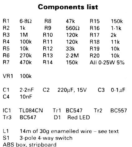
Parts List
L1 Construction
The inductor L1 is made by winding directly around the internal 4 pillars of the enclosure that may be used for screwing the PCB corners.
The number of turns can be 42, using 30 SWG super enameled copper wire. Create L1 until you have a 3.2 Ohm resistance across the winding ends, or around 90uH inductance value.
The wire thickness is not crucial, but the resistance and inductance values must be as stated above.
Test Results
With the winding details as described above a 1,000uF capacitor tested in the Cx slots should generate a frequency of 70 Hz. A 1 pF capacitor may cause an increase in this frequency to around 10 kHz.
While examining the circuit I hooked up a crystal earpiece through a 100 nF capacitor at R19 to test the frequency levels. The clicking of a square wave frequency was nicely audible while VR1 was adjusted a long way away from the location that caused the oscillations to cease. As the VR1 was being adjusted towards its critical point I could start hearing the pure sound of a low voltage sinewave frequency.
How to Calibrate
Take a high grade 1,000µF capacitor having a voltage rating of a minimum of 25 V and insert it in the Cx points. Gradually vary the VR1 until you find the LED completely switched off. Mark this specific point behind the pot scale dial as 0.1 Ω.
Next, attach a known resistor in series with the existing Cx under test which will cause the LED to light up, now again adjust VR1 until the LED is just switched OFF.
At this point mark the VR1 dial scale with the fresh total resistance value. It may be quite preferable to work with increments of 0.1Ω on the 1Ω range and suitably bigger increments on the other two ranges.
Interpreting the Results
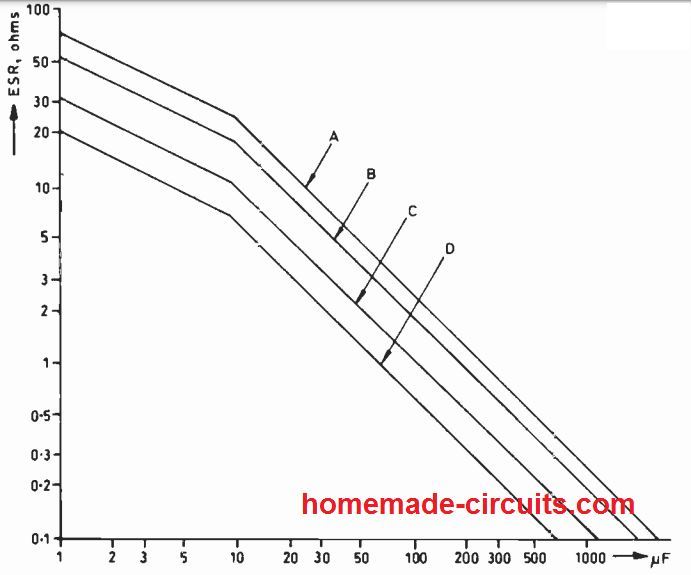
The graph below demonstrates standard ESR values, according to manufacturers' records and taking into account the fact that ESR calculated at 10 kHz is generally 1 / 3 of that tested at 1 kHz. The ESR values with 10V standard quality capacitors can be found to be 4 times higher than those with low-ESR 63V types.
Therefore, whenever a low-ESR type capacitor degrades to a level where its ESR is much like that of a typical electrolytic capacitor, its internal warming up conditions will increase 4 times higher!
In the event that you see the tested ESR value is greater than 2 times the value shown in the following figure, you may assume the capacitor no more at its best condition.
ESR values for capacitors having voltage ratings different from those indicated below will be between the applicable lines on the graph.
Comments
Hello!Swagatam
In your explanations above, you say that R = V / I will be 12 V.Is the V voltage the voltage at the 4 diode outputs 1n4007?Or is the secondary winding output voltage of the transformer?
Can you use this circuit to measure and calculate a sample capacitor esr value?
The voltage will be 12 x 1.41 = 16.92V
I installed the simple circuit shown above. I used a 0-12V / 220V transformer.Connected to a condenser of 330 microfarad-200V.I switched the digital multimeter to milliamp.Since the capacitor is charged immediately, it is difficult to read the current drawn in the ammeter.It shows the ammeter value for a very short time and then no current flow.Therefore, it is necessary to read the current drawn by the capacitor very quickly.I found the value of the 330uF-200V capacitor as follows; R=U/I=12,36/0.0188=657,44ohm Xc=4,82ohm.The esr value of this capacitor = 657.44-4.82 = 652.62ohm. Is this result correct?
Olgun, I have changed the procedure slightly, so please do it again using the new procedure.
But 330uF is too big, please first confirm using a small non polar capacitor like 1uF.
Hello!
10uf-50v ı installed a capacitor according to the new procedure.I read 32.6 ma from the ammeter.The voltage of the circuit is 12,53×1.41 = 17,667v
Xc = 159,23 ohm R = U / I = 17,667 / 0,0326 = 541,9 ohm
According to these results, what is the ESR value of the capacitor?
OK.I’il try it according to the new procedure.I’il contact you again for results.
Hi
I need a circuit for a fish tank heater.
It must keep the water at 30 degrees, and switch off and as soon as the temperature drops below 30 degrees the heater must switch back on.
Regards
You can try the second last circuit form this article:
https://www.homemade-circuits.com/how-to-build-simple-electronic/
I would be deleting this comment soon since it’s not related to ESR meter.
hi sir
is there any way to upload a picture from final circuit?
from 2 side of circuit?
any video that shows hot it works?
Hi electro kar, sorry I do not have a video for this at the moment!
Hello mr Swagatam
How to connect power supply the esr circuit above ? Is it need ground or just positive and negative supply?thanks
Ok,thanks mr.Swagatam
Hi Susilo, I have updated the diagram with the negative supply line, please check it out.
good day sir i tried your design no deflection in good caps
Hi Rodan, I am sorry it will be difficult for me to troubleshoot your circuit because the design is too elaborate and might need quite many examinations and tweaking to make it work perfectly.
What is the frequency to be used in measuring ESR? The Xc value found with 100hz will be different from the calculated value at 100khz.
The shown will show whether the capacitor is good or not, which will be applicable for all frequencies. If you want to confirm for 100kHz then you can change the set up for 100kHz
ok sir . .can you give me the pcb design of the esr tester?if its ok sir?
I may try if possible….
good day sir . . i use the anolog meter for the meter and i test the cap .the pointer didnt move . .i have no potentiometer . .
sir what is the exact numbers and letters of ic 741 . .tnx
Rodan, any 741 IC will do, the prefixes are not important.
how to determine if the capacitor is good or bad? tnx
there will be no deflection in the meter…
Very useful
Est miter circuit
Thanks,sir ji
you are welcome birbal, and dhodhy
Esr good thank for you
Dear Mr. Swagatam,
Thank you for designing the circuit. You truly are a helpful man.
Thank you dear Imanul,
you are most welcome!
Circuits for transistor check and capacitance check too would be helpful.
yes those circuits are already included in this blog, you can search them through the given search boxes
Hello Mr.Swagatham,
The esr circuit presented by your is boon for amatuer hobbyist like me as it helps to identify bad caps from salvaged caps.
I heard that ferrite transformer from mobile chargers or pc power supplies too can be used.
Thank Gururaj,
yes any type of ferrite core can be tried for the transformer