A configuration in which a bipolar junction transistor or a BJT is reinforced with an emitter resistor for enhancing its stability with regards to changing ambient temperatures, is called an emitter stabilized bias circuit for BJT.
We have already studied what is DC biasing in transistors, now let's move ahead and learn how an emitter resistor can be used for improving the stability of a BJT DC bias network.
Applying Emitter Stabilized Bias Circuit
The inclusion of the emitter resistor to the dc bias of the BJT delivers superior stability, meaning, the dc bias currents and voltages continue to be more close to where they had been fixed by the circuit considering external parameters, such as variations in temperature, and transistor beta (gain),
The below given figure shows a transistor DC bias network having an emitter resistor for enforcing an emitter-stabilized biasing on the existing fixed bias configuration of the BJT.

Figure 4.17 BJT Bias Circuit with Emitter Resistor
In our discussions we'll begin our analysis of the design by first inspecting the loop around the base-emitter region of the circuit, and then use the results for further investigating the loop around the collector-emitter side of the circuit.
Base-Emitter Loop

We can redraw the above base-emitter loop in the way shown below in Fig 4.18, and if we apply Kirchhoff's voltage law on this loop in the clockwise direction, helps us to get the following equation:
+Vcc = IBRB - VBE - IERE = 0 -------(4.15)
From our previous discussions we know that: IE = (β+1)IB -------(4.16)
Substituting the value of IE in Eq.(4.15) provides the following result:
Vcc = IBRB - VBE - (β+1)IBRE = 0
Putting the terms in their respective groups yields the following:

If you recall from our previous chapters, the fixed bias equation was derived in the following form:
If we compare this fixed bias equation with the (4.17) equation we find the only difference between the two equation for current IB is the the term (β+1)RE.
When the equation 4.17 is used for drawing a series based configuration we are able to extract an interesting result, which actually is the similar to equation 4.17.

Take the example of the following network in Fig 4.19:
If we solve the system for current IB, results in the same equation obtained in Eq. 4.17. Observe that besides the voltage from base to emitter VBE, the resistor RE could be seen appearing again at the input of the base circuit by a level (β+1).
Meaning, the emitter resistor which forms a part of the collector-emitter loop shows up as (β+1)RE in the base-emitter loop.
Assuming that β could be mostly above 50 for most BJTs, the resistor at the emitter of the transistors could be significantly bigger in the base circuit. Hence, we are able to derive the following general equation for the Fig.4.20:
Ri = (β+1)RE ------(4.18)
You will find this equation quite handy while solving many future networks. Actually, this equation facilitates memorizing equation 4.17 in an easier way.
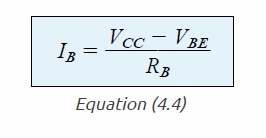
As per Ohm's law we know that the current through a network is the voltage divided by the resistance of the circuit.
The voltage for a base-emitter design is = Vcc - VBE
The resistances seen in the 4.17 are RB + RE, which is reflected as (β+1), and the result is what we have in Eq 4.17.
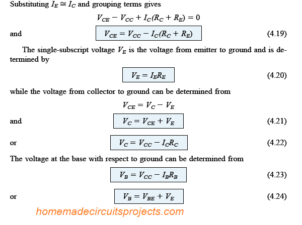
Collector–Emitter Loop

The figure above shows the collector-emitter loop, applying Kirchhoff's law to the indicated loop in the clockwise direction, we get the following equation:
+IERE + VCE + ICRC - VCC = 0

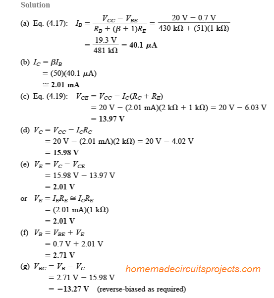
Solving a practical example for an emitter stabilized bias circuit as given below:
For the emitter bias network as given in the above figure 4.22, evaluate the following:
- IB
- IC
- VCE
- VC
- VE
- VB
- VBC
Determining Saturation level

The maximum collector current which becomes the collector saturation level for an emitter bias network could be calculated by employing the identical strategy which had been applied for our earlier fixed bias circuit.

It may be implemented by creating a short circuit across the collector and emitter leads of the BJT, as indicated in the above diagram 4.23, and then we can evaluate the resulting collector current using the following formula:
Example problem for solving saturation current in an emitter stabilized BJT circuit:


Load Line Analysis
The load-line analysis of the emitter-bias BJT circuit is quite similar to our earlier discussed fixed-bias configuration.
The only difference being the level of IB [as derived in our Eq.(4.17)] defines the level of IB on the characteristics as shown in the following Fig. 4.24 (indicated as IBQ).


Comments
I use a transistor to drive a 12 volts relay. I use a resistor to stabilize the emitter. Yet, whenever I change the value of the resistor voltages change at the emitter as well as at the collector and there is difficulty getting that level of voltage I put a LED to indicate the output. Rather confusing is that if the position of the transistor changed and the emitter is connected to the Vcc rather than being grounded the circuit still gives output. I noticed also that Vb may be smaller or bigger than the assumed 0.7 voltage drop and this doesn’t disrupt the output. There a way to fix these issues but here I’ll appreciate help.
I have never used a emitter resistor for a relay driver transistor? What happens if you remove the emitter resistor and connect the emitter directly to the ground?
Regarding the input impedance,
I failed to understand why the base resistance is bigger than “(beta +1)Re” in your example
of Rb= 430k Ohms, and Re= 1k Ohms, when you need the base resistance to be around 100 times smaller than “(beta+1)Re”. what I understood is that if base resistance is small enough, the collector current will be almost independent of Beta or changes in temperatures to the resistor. Ic=beta*Ib
Can you please clarify this for me, as I don’t quit understand this part fully?
Thank you in advance.