• Skip to main content
  • Skip to primary sidebar

Homemade Circuit Projects

Need circuit help? Post them in the comments! I've answered over 50,000!

Blog | Categories | About | Contact | Calculators-online
You are here: Home / Water Controller / How to Measure Dissolved Oxygen in Liquids

How to Measure Dissolved Oxygen in Liquids

Last Updated on April 19, 2020 by Swagatam 3 Comments

In this post I have explained a sensor device used for measuring the level or amount of dissolved oxygen in water and other fluids. The idea was requested by Mr. Amit

Technical Specifications 

I didn't find sensors or sensor modules for Dissolved Oxygen or pH readings for us to use with controllers for our projects. but we get sensors with controllers with display which are expensive.

Do you have any idea?

Thanks

Analyzing the Circuit Query

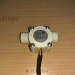
Sensors for measuring dissolved oxygen are available ready made in the market, one such example may be seen below:

dissolvedoxygensensor 1

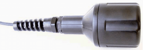
The output can be easily integrated with an external amplifier circuit for the required conversions or displays.

If possible I'll try to update the info in my blog soon with all the details.

The Design

Today companies manufacture numerous types of sensors for measuring oxygen in water known as Dissolved Oxygen sensors, which you can use in water, chemical processor jobs, laboratory, and ecological .Dissolved oxygen (DO) is the expression or the evaluation of the oxygen dissolved in a unit volume of water, generally in units of mg/L or ppm.

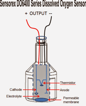
The preferred sensing unit may comprise of 2 electrodes, an anode and cathode, in electrolyte and from the water in question by an oxygen permeable membrane, as observed in Figure 2.

Oxygen diffuses across the membrane and interacts with the cathode to a potential difference proportional to the oxygen diffused into the sensor.

DO sensors consequently basically determines the deficient strain of the oxygen in water; permits extra oxygen to across the membrane and more voltage to be generated. The current is then converted into a millivolt output, that could be assessed with a WSN wireless node.

The type of dissolved oxygen sensor shown above are quite ideal since the output can be quickly accessed and interfaced with any desired measuring instrument such as a millivoltmeter, LED bar graph meter, transistorized amplifier, opamp based amplifier etc for translating the collected data into the the required levels so that it can be assessed appropriately for the results.

The internal view of the above example sensor may be witnessed in the following image:

Sensor Setup

The shown outputs provides a direct readable data in the form of millivolts which could be used for for triggering an external electronic circuit stage.

You'll also like:

  • 1.  SMS Based Water Supply Alert System
  • 2.  Industrial Tank water fill/drain controller Circuit
  • 3.  Making a Float Switch Circuit for a Corrosion-free Water Level Control
  • 4.  Ultrasonic Wireless Water Level Indicator – Solar Powered
  • 5.  Analogue Water Flow Sensor/Meter Circuit – Check Water Flow Rate
  • 6.  Capacitive Fluid Meter Circuit for Sealed Tanks

About Swagatam

I am an electronics engineer with over 15 years of hands-on experience. I am passionate about inventing, designing electronic circuits and PCBs, and helping hobbyists bring their projects to life. That is why I founded homemade-circuits.com, a website where I share innovative circuit ideas and tutorials. Have a circuit related question? Leave a comment.... I guarantee a reply!

Previous Post: « Digital Up/Down Volume Control Circuit
Next Post: LED Brightness and Efficiency Tester Circuit »

Reader Interactions

Comments

  1. silo weighing says

    September 9, 2020 at 12:56 pm

    This article provides us information regarding the virtual commissioning the solution you needed to know. It provide us true and insightful information regarding it .So, anyone searching for same topic may find their shelter over here. This is a great article and you are banged on with your points about it.

    Reply
  2. VENKATARAMAKRISHNAREDDY TETALI says

    April 26, 2017 at 12:31 pm

    did any one found solution for the DO circuit

    Reply
    • Kim JC says

      August 1, 2019 at 6:49 pm

      great !!!!
      I am interested in DO sensors
      I’ve tried this one, but I want to make it once for the optical sensor. I will post it.

      thanks.

      Reply

Need Help? Please Leave a Comment! We value your input—Kindly keep it relevant to the above topic! Cancel reply

Your email address will not be published. Required fields are marked *

Primary Sidebar

Subscribe to New Circuit Ideas

Categories

  • Arduino Projects (87)
  • Audio and Amplifier Projects (132)
  • Automation Projects (17)
  • Automobile Electronics (101)
  • Battery Charger Circuits (82)
  • Datasheets and Components (102)
  • Electronics Theory (143)
  • Free Energy (37)
  • Games and Sports Projects (11)
  • Grid and 3-Phase (19)
  • Health related Projects (25)
  • Home Electrical Circuits (12)
  • Indicator Circuits (14)
  • Inverter Circuits (87)
  • Lamps and Lights (142)
  • Meters and Testers (69)
  • Mini Projects (46)
  • Motor Controller (64)
  • Oscillator Circuits (27)
  • Pets and Pests (15)
  • Power Supply Circuits (108)
  • Remote Control Circuits (50)
  • Security and Alarm (64)
  • Sensors and Detectors (100)
  • Solar Controller Circuits (59)
  • Temperature Controllers (42)
  • Timer and Delay Relay (49)
  • Transmitter Circuits (29)
  • Voltage Control and Protection (37)
  • Water Controller (36)

Calculators

  • Battery Back up Time Calculator
  • Capacitance Reactance Calculator
  • IC 555 Astable Calculator
  • IC 555 Monostable Calculator
  • Inductance Calculator
  • LC Resonance Calculator
  • LM317, LM338, LM396 Calculator
  • Ohm’s Law Calculator
  • Phase Angle Phase Shift Calculator
  • Power Factor (PF) Calculator
  • Reactance Calculator
  • Transistor Astable Calculator
  • Transistor base Resistor Calculator
  • Voltage Divider Calculator
  • Wire Current Calculator
  • Zener Diode Calculator
  • Filter Capacitor Calculator
  • Buck Converter Calculator
  • Boost Converter Calculator
  • Solar Panel, Inverter, Battery Calculator
  • Wire Current Calculator
  • SMPS Transformer Calculator
  • IC SG3525, SG3524 Calculator
  • Inverter LC Filter Calculator

People Also Search

555 Circuits | 741 Circuits | LM324 Circuits | LM338 Circuits | 4017 Circuits | Ultrasonic Projects | SMPS Projects | Christmas Projects | MOSFETs | Radio Circuits | Laser Circuits | PIR Projects |

Recent Comments

  • Swagatam on Simple Delay Timer Circuits Explained
  • Swagatam on The Role of Inductor Coil in SMPS
  • Swagatam on 7 Modified Sine Wave Inverter Circuits Explored – 100W to 3kVA
  • Swagatam on 7 Modified Sine Wave Inverter Circuits Explored – 100W to 3kVA
  • Victor on 7 Modified Sine Wave Inverter Circuits Explored – 100W to 3kVA

Company

  • Privacy Policy
  • Cookie Policy
  • About Me
  • Contact
  • Disclaimer
  • Copyright
  • Videos
  • Sitemap

Social Profiles

  • Twitter
  • YouTube
  • Instagram
  • Pinterest
  • My Facebook-Page
  • Quora
  • Stack Exchange
  • Linkedin
  • © 2025 · Swagatam Innovations