• Skip to main content
  • Skip to primary sidebar

Homemade Circuit Projects

Need circuit help? Post them in the comments! I've answered over 50,000!

Blog | Categories | About | Contact | Calculators-online
You are here: Home / Sensors and Detectors / Differential Temperature Detector/Controller Circuit


Differential Temperature Detector/Controller Circuit

Last Updated on March 20, 2019 by Swagatam 6 Comments

The circuit identifies and detects the temperature difference between two sensors and activates a relay when the temperature is not identical on these differently positioned sensors.

Table of Contents
  • Operational Details
  • Circuit Diagram

By: Manisha Patel

It'll also enable you to detect a difference in temperature, although the temperature sensing devices can be set are discretely, using a potentiometer.

Operational Details

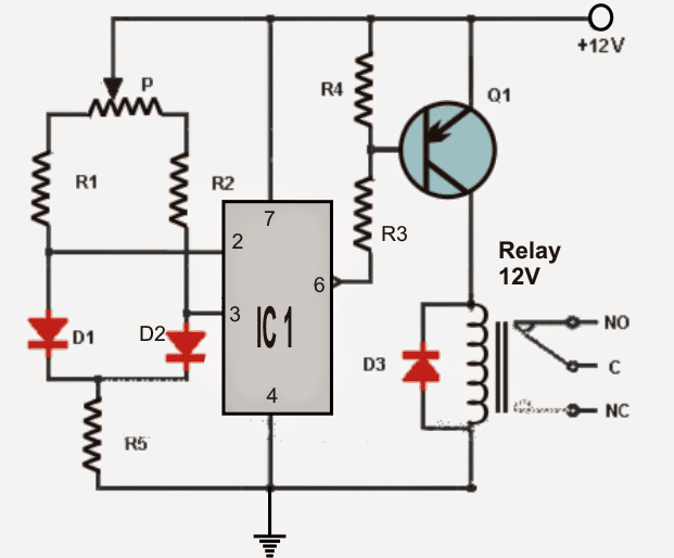
To implement the sensing abilities a couple of ordinary "garden" diodes are used as temperature sensors (D1 and D2).

As the anodes of both the diodes are attached with the inputs of an opamp it works like a comparator, configured to detect any temperature difference to cause it to output a low voltage.

These diodes should be positioned over two distant desired locations across which the temperatures may be required to be compared. The sensors are capable of detecting even the slightest amount temperature variation across each other.

- If the diode D1 is placed in a questionable place where the temperature relatively decreases, the opamp gives an output low and activates the relay through the via the transistor Q1. The transistor may be used to activate a heating system or similar with an intention of restoring the decrease in the temperature..

- Identically if the diode D2 is positioned across a susceptible premise to sense an increase in temperature, the opamp gives an output low again activating the relay through the transistor Q1. In this application the transistor/relay may be employed for activating a cooler system or a fan.

In an event when the temperature of the two diodes are restored to equal temperatures, the relay is deactivated.

It must be noted that the inclusion of the potentiometer is to vary the sensing levels of the circuit as per the user preference.

Note: The circuit can be powered by 9V battery. The relay should also be rated at the same voltage as the supply.

Circuit Diagram

warning message: electricity is dangerous, proceed with caution
differentialtemperatureindicatorcircuit 1

List of components for the above differential temperature detector circuit:

- IC1: operational amplifier 741.
- Q1: PNP BC557
- R1 = R2: 4.7K
- R3 = R4: 1.2K
- R5: 2.7K
- P: 100K pot
- D1 = D2 = D3: diode 1N4001
- RL1: 12V relay.
You'll also like:

  • 1.  Simple Vibration Sensor Circuit
  • 2.  Tuned Infrared (IR) Detector Circuit
  • 3.  How to Connect a TSOP1738 IR Sensor
  • 4.  2 Useful Energy Saver Solder Iron Station Circuits
  • 5.  Very Low Frequency (VLF) Detector Circuit
  • 6.  Precision Current Sensing and Monitoring Circuit using IC NCS21xR

Filed Under: Sensors and Detectors, Temperature Controllers Tagged With: Controller, Detector, Differential, Temperature

About Swagatam

I am an electronics engineer and doing practical hands-on work from more than 15 years now. Building real circuits, testing them and also making PCB layouts by myself. I really love doing all these things like inventing something new, designing electronics and also helping other people like hobby guys who want to make their own cool circuits at home.

And that is the main reason why I started this website homemade-circuits.com, to share different types of circuit ideas..

If you are having any kind of doubt or question related to circuits then just write down your question in the comment box below, I am like always checking, so I guarantee I will reply you for sure!

Previous Post: « 4 LED Temperature Indicator Circuit
Next Post: Power Interruption Alarm Circuit for Instant Power Failure Indications »

Reader Interactions

Comments

  1. Prakash Srivastava says

    January 1, 2021 at 10:57 am

    Dear Swagatam,
    First of all wish you a very happy new year 2021.
    We made the above temperature controller circuit. But unfortunately it is not sensing the temperature with diode D1 and D2. The question is, how a diode can work as temperature sensor?
    Should we use some temperature sensor, instead of diode D1 and D2?

    Reply
    • Swagatam says

      January 1, 2021 at 11:40 am

      Thank you Dear Prakash, and wish you too a Happy 2021.

      This design was submitted to me by an eternal author, but it seems the circuit should work.
      All semiconductors respond to temperature changes by altering their forward voltage drop.
      A 1N4148 diode will likewise will show a reduction in its forward voltage by 2 mV in response to every 1 degree rise its body temperature. Meaning, its normal 0.6V forward drop will keep reducing by 2mV for each degree rise in temperature.

      Reply
  2. Abdelkarim BAYNHOU says

    April 2, 2016 at 3:38 am

    What component used to detect temperature difference in this circuit

    Reply
    • Swagatam says

      April 2, 2016 at 5:01 am

      D1 and d2

      Reply
  3. Pritam Bhowmik says

    February 1, 2015 at 9:07 am

    1N4007 can be used?

    Reply
    • Swagatam says

      February 2, 2015 at 5:48 am

      yes can be used

      Reply

Need Help? Please Leave a Comment! We value your input—Kindly keep it relevant to the above topic! Cancel reply

Your email address will not be published. Required fields are marked *

Primary Sidebar

circuit simulator image

Subscribe to New Posts


Categories

  • Arduino Projects (89)
  • Audio and Amplifier Projects (132)
  • Automation Projects (17)
  • Automobile Electronics (101)
  • Battery Charger Circuits (83)
  • Datasheets and Components (104)
  • Electronics Theory (143)
  • Free Energy (37)
  • Games and Sports Projects (11)
  • Grid and 3-Phase (19)
  • Health related Projects (25)
  • Home Electrical Circuits (12)
  • Indicator Circuits (14)
  • Inverter Circuits (88)
  • Lamps and Lights (142)
  • Meters and Testers (69)
  • Mini Projects (46)
  • Motor Controller (64)
  • Oscillator Circuits (27)
  • Pets and Pests (15)
  • Power Supply Circuits (108)
  • Remote Control Circuits (50)
  • Security and Alarm (64)
  • Sensors and Detectors (101)
  • Solar Controller Circuits (59)
  • Temperature Controllers (42)
  • Timer and Delay Relay (49)
  • Transmitter Circuits (29)
  • Voltage Control and Protection (39)
  • Water Controller (36)


Other Links

  • Privacy Policy
  • Cookie Policy
  • Disclaimer
  • Copyright
  • Videos
  • Sitemap


People also Search

555 Circuits | 741 Circuits | LM324 Circuits | LM338 Circuits | 4017 Circuits | Ultrasonic Projects | SMPS Projects | Christmas Projects | MOSFETs | Radio Circuits | Laser Circuits | PIR Projects |

Social Profiles

  • Twitter
  • YouTube
  • Instagram
  • Pinterest
  • My Facebook-Page
  • Quora
  • Stack Exchange
  • Linkedin


  • Recent Comments

    • Swagatam on How Shunt Regulator TL431 Works, Datasheet, Application
    • SA on How Shunt Regulator TL431 Works, Datasheet, Application
    • Farmtech on Free Energy Generator Circuit – The N-Machine
    • Nitesh Agrawal on How to Design Simple LED Driver Circuits
    • Swagatam on How to Design Simple LED Driver Circuits

    © 2025 · Swagatam Innovations