• Skip to main content
  • Skip to primary sidebar

Homemade Circuit Projects

Need circuit help? Post them in the comments! I've answered over 50,000!

Blog | Categories | About | Contact | Calculators-online
You are here: Home / Lamps and Lights / Corona Effect Generator Circuit

Corona Effect Generator Circuit

Last Updated on January 12, 2024 by Swagatam 2 Comments

In this post we study regarding what is corona effect and how to make a corona effect generator circuit at home using a CDI coil and a tesla coil configuration. Then idea was suggested by Mr. Sanjoy

Table of Contents
  • Corona Treatment for Paper Coating
  • The Design

mon thumb1 2

Corona Treatment for Paper Coating

Many many thanks for posting the alternate switching timer circuit as requested. Although I haven't tried yet, but your circuits work mostly.

Here us another request . In our paper coating lab, we are trying to coat OHP polyester sheets with the same formulation as paper coating.

But the problem we are facing is the low surface tension of the polyester sheets. The applied coating isn't spreading evenly and forming droplets as well. To overcome this problem we need a handheld Corona Treatment device.

Which will be able to produce high density concentrated corona along the edge of a 15 inches long ideal discharge line. It will be better if the circuit can be designed transformer less.

Please advice regarding the design of insulated handle as well. The device will be turned on and swept lightly and slowly over the surface of the polyester sheet from a very close distance.

This way the corona bombarded surface will have higher level of surface tension and can be coated properly.

SANJOY BHATTACHARJEE

The Design

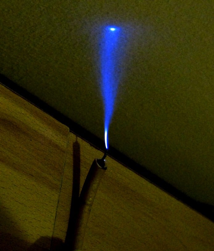
A corona discharge effect can be generally visualized in darkness around high voltage sources ranging from 2kV and above.

The corona effect is created by the emission of ions from a high voltage source due to the immense voltage pressure from the source.

The high voltage pressure causes charging up of the air atoms around the conductor forming a shining crown like structure, hence the name "corona"

This basically happens due to the absence of a neutral or ground nearby, which causes huge electrical pressure build up around the source forcing the air around it to charge up into ions. However if a ground or a neutral line becomes available somewhere within the reach of the source could normally cause the high voltage to jump across the gap giving rise to sparks and arcing.

A practical example of corona discharge could be seen around high tension overhead wiring which normally carry many kVs of potential, the same could be also witnessed around flyback transformer cable used in old vacuum tube TV sets.

A small scale model of corona effect generator circuit can be built using any high voltage generator circuit.

I have discussed an air ionizer circuit in one of my earlier posts, the tip of the needle connected with the circuit could be seen with a tiny blue corona discharge in complete darkness, especially when we hold our finger little above the needle point.

A full fledged corona discharge could be probably built using a CDI coil circuit in conjunction with a small tesla coil.

A CDI coil circuit can be built from the many relevant links provided in the website.

Once the CDI coil circuit is built, the output of the CDI coil could be configured with a homemade tesla coil circuit for visualizing a breathtaking corona effect in darkness.

You'll also like:

  • 1.  Variable LED Intensity Controller Circuit
  • 2.  LED Light Wave Effect Generator Circuit
  • 3.  Automatic Night Activated Wireless Light Circuit for Paintings
  • 4.  Simple LED Circuits
  • 5.  1 watt LED Lamp Circuit Diagram using SMD LEDs
  • 6.  0.6V to 6V/12V Boost Converter Circuit Diagram

About Swagatam

I am an electronics engineer with over 15 years of hands-on experience. I am passionate about inventing, designing electronic circuits and PCBs, and helping hobbyists bring their projects to life. That is why I founded homemade-circuits.com, a website where I share innovative circuit ideas and tutorials. Have a circuit related question? Leave a comment.... I guarantee a reply!

Previous Post: « Make this 7 Segment Digital Clock with Beep Alert Circuit
Next Post: Beacon Level Indicator Circuit for Combine Harvester Grain Tanks »

Reader Interactions

Comments

  1. Success Ola says

    August 12, 2016 at 5:48 am

    Hello sir

    I have been working on a RC plane for like a month now sir. But I don't know to connect it wireless, such that there will be a knob switch to control the speed of the motor and 4 push button switch, 2 of the push button will be working with each of the 2 servo,And can control it to go forward and reverse

    Reply
    • Swagatam says

      August 12, 2016 at 1:20 pm

      Hello Success, you can refer to this concept:

      https://www.homemade-circuits.com/2016/06/rc-helicopter-remote-control-circuit.html

      please comment under the above linked article for further discussions.

      Reply

Need Help? Please Leave a Comment! We value your input—Kindly keep it relevant to the above topic! Cancel reply

Your email address will not be published. Required fields are marked *

Primary Sidebar

Subscribe to New Circuit Ideas

Categories

  • Arduino Projects (87)
  • Audio and Amplifier Projects (132)
  • Automation Projects (17)
  • Automobile Electronics (101)
  • Battery Charger Circuits (83)
  • Datasheets and Components (104)
  • Electronics Theory (143)
  • Free Energy (37)
  • Games and Sports Projects (11)
  • Grid and 3-Phase (19)
  • Health related Projects (25)
  • Home Electrical Circuits (12)
  • Indicator Circuits (14)
  • Inverter Circuits (87)
  • Lamps and Lights (142)
  • Meters and Testers (69)
  • Mini Projects (46)
  • Motor Controller (64)
  • Oscillator Circuits (27)
  • Pets and Pests (15)
  • Power Supply Circuits (108)
  • Remote Control Circuits (50)
  • Security and Alarm (64)
  • Sensors and Detectors (101)
  • Solar Controller Circuits (59)
  • Temperature Controllers (42)
  • Timer and Delay Relay (49)
  • Transmitter Circuits (29)
  • Voltage Control and Protection (37)
  • Water Controller (36)

Calculators

  • Battery Back up Time Calculator
  • Capacitance Reactance Calculator
  • IC 555 Astable Calculator
  • IC 555 Monostable Calculator
  • Inductance Calculator
  • LC Resonance Calculator
  • LM317, LM338, LM396 Calculator
  • Ohm’s Law Calculator
  • Phase Angle Phase Shift Calculator
  • Power Factor (PF) Calculator
  • Reactance Calculator
  • Transistor Astable Calculator
  • Transistor base Resistor Calculator
  • Voltage Divider Calculator
  • Wire Current Calculator
  • Zener Diode Calculator
  • Filter Capacitor Calculator
  • Buck Converter Calculator
  • Boost Converter Calculator
  • Solar Panel, Inverter, Battery Calculator
  • Wire Current Calculator
  • SMPS Transformer Calculator
  • IC SG3525, SG3524 Calculator
  • Inverter LC Filter Calculator

People Also Search

555 Circuits | 741 Circuits | LM324 Circuits | LM338 Circuits | 4017 Circuits | Ultrasonic Projects | SMPS Projects | Christmas Projects | MOSFETs | Radio Circuits | Laser Circuits | PIR Projects |

Recent Comments

  • Swagatam on AC Motor Speed Controller Circuits using Back EMF
  • Swagatam on DC to DC Converter Circuits using SG3524 [Buck, Boost Designs]
  • Swagatam on Understanding SG3525 IC Pinouts
  • Swagatam on 7 Simple Inverter Circuits you can Build at Home
  • Swagatam on Timer Based Cell Phone Charger Circuit

Company

  • Privacy Policy
  • Cookie Policy
  • About Me
  • Contact
  • Disclaimer
  • Copyright
  • Videos
  • Sitemap

Social Profiles

  • Twitter
  • YouTube
  • Instagram
  • Pinterest
  • My Facebook-Page
  • Quora
  • Stack Exchange
  • Linkedin
  • © 2025 · Swagatam Innovations