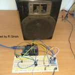
Many people build inverter using EGS002, then they ask can we connect normal 16×2 LCD or not?? So the answer is yes, but not the way you may think.
Understanding LCD Side Of EGS002
As we all know EGS002 is built around EG8010. That chip is dedicated SPWM sine wave inverter controller IC, which handles SPWM generation, MOSFET drive timing, protection logic, voltage and frequency control and also LCD data output.
Now important thing is that the LCD interface of EG8010 is not normal parallel type like Arduino uses, it is very different.
It gives only three pins:
+5V
GND
LCD DATA
So this is just a serial output. So is It Normal UART Type?
Here confusion starts. It is serial, yes but not guaranteed normal ASCII UART like Arduino TX.
The protocol is fixed inside EG8010 firmware and that can not be changed. This feature was made mainly for its own matching LCD module.
So if you connect random UART serial LCD, then maybe it works or maybe not. It may not be safe to assume.
Can We Use Standard 16×2 Parallel LCD?

Simple answer....No.
Standard 16×2 LCD, HD44780 type, needs RS, E, RW, D4 to D7 or full D0 to D7, but EGS002 gives only one data line. So it can not be used to drive that directly.
So if you have a standard 16 pin 16×2 LCD, then no direct connection possible with EGS002 module.
So Can We Use I2C 16×2 LCD?
Answer is again, No.
I2C LCD needs SDA and SCL. EG8010 does not output I2C, it outputs its own serial format, so if you connect I2C directly, then it will show nothing....
Connecting A 16×2 Serial LCD With EGS002 – Full Wiring Guide
The board in the below given image, is the EGS002 front view version, and it has a separate LCD Port already there on the board.
It is built around EG8010, and in this version the LCD side is taken out as a 7-pin synchronous serial connector, so now it is not like normal LCD wiring.
Important thing, understand this clearly.
- This is NOT UART TX type.
- This is NOT I2C.
- This is NOT parallel HD44780 type wiring.
It is a dedicated synchronous interface which is made only for the official EG8010 compatible LCD module, so if you try anything else then it will not behave.
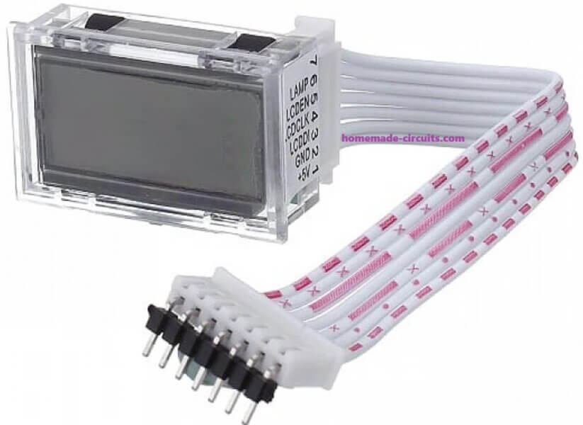
Now let us see the LCD Port pins.

From our image the pins are marked like this:
1 = +5V
2 = GND
3 = DIN
4 = CLK
5 = EN
6 = LED+
7 = LED−
These give power and ground, also DIN which is serial data, CLK which is clock, EN which is enable control, and LED+ LED− for backlight, so that is all coming directly from the board.
Now LCD type.
You must use the official EG8010 compatible 16×2 LCD module which supports DIN, CLK, EN. If you use a normal 16-pin parallel LCD then it will not work. If you use 3-pin UART LCD then also it will not work. If you use I2C backpack LCD then again it will show dead response. So since this is synchronous type, therefore only EG8010 compatible module works, as shown below.
Now wiring, which is simple but you must match pin to pin.
- EGS002 Pin 1 (+5V) = LCD VCC
- EGS002 Pin 2 (GND) = LCD GND
- EGS002 Pin 3 (DIN) = LCD DIN
- EGS002 Pin 4 (CLK) = LCD CLK
- EGS002 Pin 5 (EN) = LCD EN
- EGS002 Pin 6 (LED+) = LCD Backlight +
- EGS002 Pin 7 (LED−) = LCD Backlight −
After this nothing extra is needed... It just connects and runs.
How it Works
Internally EG8010 measures output voltage, it detects 50Hz or 60Hz frequency, watches protection faults, and if temperature sensor is connected then it reads heat sink temperature also, then it formats all this data and sends synchronized pulses through DIN, CLK, EN.
The compatible LCD understands that format, so when power is applied then display immediately shows AC Output Voltage, Frequency, status, faults, temperature if sensor is there. Everything handled by EG8010 firmware, so you do not touch anything.
Now practical side, which is important because inverter is noisy.
Important Notes
Make sure LCD wires are short. If wires are long then noise can enter, then display may flicker. Keep the DIN, CLK, EN away from MOSFET gate lines. Keep cable away from transformer primary. Ensure common ground is solid. If yo see noise appears then add 100uF capacitor across LCD VCC and GND near LCD, then it might usually settle.
Do not try experiments here. If you connect 16-pin HD44780 directly then it will not respond, also if you connect I2C SDA/SCL type then again nothing, with UART RX LCD it will be also dead. Since this interface is synchronous and proprietary therefore other types will not understand the signal.
So final thing, for this EGS002 board version, LCD support is there, it is 7-pin synchronous serial type, only official EG8010 compatible LCD module should be used, no external controller needed. This is the safest way and if you wire correctly then it works....
Backlight part.
Most serial LCD modules already have built in backlight resistor and contrast preset, so we do not touch anything here.
If your module does not have it then connect backlight anode to +5V through 100 ohm to 220 ohm resistor, and cathode to GND, otherwise then LED may burn.
Using a Microcontroller Between EGS002 (7-Pin LCD Port) and a Normal 16×2 LCD
If you want to use a normal parallel or I2C 16×2 LCD then you must place a microcontroller in between.
But here is the important part....This version does NOT output UART serial, it only outputs synchronous serial data using:
DIN = Data
CLK = Clock
EN = Frame Enable
So your MCU must capture data bit-by-bit using the clock signal.
How the Interface Works...
Typical behavior (just conceptually):
- EN goes HIGH = Start of frame.
- CLK toggles = Each clock pulse shifts one bit.
- DIN carries the data bit.
- When EN goes LOW = Frame complete.
So the microcontroller must:
- Detect EN rising edge,
- While EN is HIGH, sample DIN on each CLK edge,
- Then store bits into buffer,
- then decode frame,
- Finally display decoded values,.
Since EG8010 protocol is fixed and not officially documented publicly, decoding requires observation or logic analyzer capture.
For demonstration only we will assume:
- Frame is 32 bytes long
- Data is ASCII formatted
(This is only for learning structure.)
Hardware Connections (7-Pin Version)

EGS002 with Arduino:
DIN goes to Arduino Pin 8
CLK goes to Arduino Pin 2 (Interrupt Pin)
EN goes to Arduino Pin 3
GND goes to Arduino GND
+5V may power Arduino if required....
Arduino with Parallel 16×2 LCD:
RS goes to Pin 7
E goes to Pin 6
D4 goes to Pin 5
D5 goes to Pin 4
D6 goes to Pin 9
D7 goes to Pin 10
Arduino Code for Synchronous Data Capture
This example captures bits on rising edge of CLK while EN is HIGH.
#include <LiquidCrystal.h>LiquidCrystal lcd(7, 6, 5, 4, 9, 10);#define DIN_PIN 8
#define CLK_PIN 2
#define EN_PIN 3volatile byte currentByte = 0;
volatile int bitCount = 0;
volatile int byteIndex = 0;#define FRAME_SIZE 32
volatile byte frameBuffer[FRAME_SIZE];void setup()
{
  pinMode(DIN_PIN, INPUT);
  pinMode(CLK_PIN, INPUT);
  pinMode(EN_PIN, INPUT);  attachInterrupt(digitalPinToInterrupt(CLK_PIN), clockISR, RISING);  lcd.begin(16, 2);
  lcd.print("Waiting Data");
}void loop()
{
  if (byteIndex >= FRAME_SIZE)
  {
    noInterrupts();
    byteIndex = 0;
    interrupts();    displayFrame();
  }
}void clockISR()
{
  if (digitalRead(EN_PIN) == HIGH)
  {
    currentByte <<= 1;    if (digitalRead(DIN_PIN))
      currentByte |= 1;    bitCount++;    if (bitCount == 8)
    {
      if (byteIndex < FRAME_SIZE)
        frameBuffer[byteIndex++] = currentByte;      bitCount = 0;
      currentByte = 0;
    }
  }
}void displayFrame()
{
  lcd.clear();
  lcd.setCursor(0, 0);  for (int i = 0; i < 16; i++)
    lcd.print((char)frameBuffer[i]);  lcd.setCursor(0, 1);  for (int i = 16; i < 32; i++)
    lcd.print((char)frameBuffer[i]);
}
What This Code Does
- Interrupt triggers on each CLK rising edge.
- If EN is HIGH then it shifts DIN bit into a byte.
- After 8 bits, it stores one byte.
- After full frame it displays content.
Very Important thing:
This example assumes the following:
- MSB-first transmission..
- Fixed 32-byte frame.
- ASCII data.
Actual EG8010 protocol may differ.
You may need to do these:
- Change bit order
- Detect EN rising edge separately
- Adjust frame length
- Decode binary fields instead of ASCII
I recommend the following:
Use a logic analyzer first to capture DIN/CLK/EN timing.
If Using I2C LCD Instead
Replace LCD section with:
#include <Wire.h>
#include <LiquidCrystal_I2C.h>LiquidCrystal_I2C lcd(0x27, 16, 2);
The capture logic remains identical.
Temperature sensor part, optional but useful.
If you connect temperature sensor to EGS002, then LCD will automatically show heat sink temperature, and if overheating happens then fault message will appear, so no extra LCD wiring needed.
After power ON, what happens.
When inverter starts, EG8010 initializes, then it begins sending serial data through TX automatically.
LCD receives data and displays AC output voltage, frequency 50Hz or 60Hz, fault status, temperature if sensor is installed.
No programming required from your side, firmware inside EG8010 handles everything.
Now some practical things. Since this is an inverter circuit, make sure to keep LCD wires away from MOSFET gate drive lines because if they run parallel then noise may get injected.
Keep wires away from transformer primary also, since high current switching is there. If wiring is long then use twisted pair for TX and GND, so noise can be reduced. Do not exceed 5V on LCD supply, otherwise LCD controller may get damaged.
If noise appears on display then add 100uF capacitor across LCD VCC and GND near the LCD module, that usually stabilizes it.
That is a complete wiring,