• Skip to main content
  • Skip to primary sidebar

Homemade Circuit Projects

Need circuit help? Post them in the comments! I've answered over 50,000!

Blog | Categories | About | Contact | Calculators-online
You are here: Home / Arduino Projects / Arduino Random RGB Light Generator Circuit

Arduino Random RGB Light Generator Circuit

Last Updated on December 5, 2024 by Swagatam 1 Comment

The  article discusses a simple,Arduino red, green, blue LED light effect generator circuit in a random pattern.

In one of the earlier posts we came across a similar RGB LED effect generator circuit using Arduino which was programmed to produce the effect in a flowing sequential manner, whereas here the set up can be expected to generate randomly changing RGB LED effect.

Hardware Required

What you will need for making this system:

1) An Arduino Board

2) A RGB LED

3) A 220 Ohm 1/4 watt resistor

4) A 9V AC to DC adapter Unit

Once you have acquired the above units, it's just about programming the Arduino IC with the following sample code, and subsequently integrating the LED, resistor and the power supply with the Arduino board as shown below:

Arduino Random RGB Light Generator Circuit

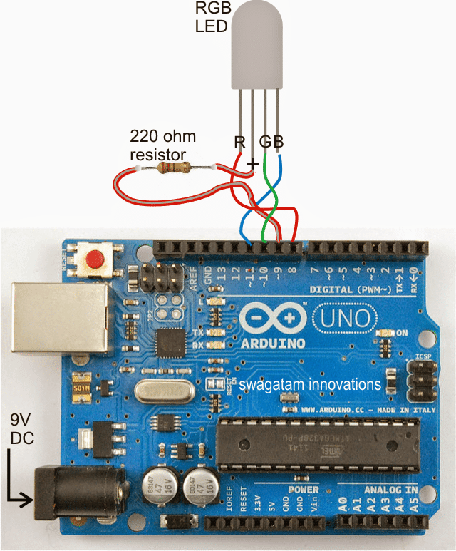
How to Wire Arduino with LED

The set up appears to be exactly similar to our previous RGB Arduino project, yes it is so, except the program which has been now changed for generating a random RGB LED light effect rather than the earlier sequentially flowing RGB color effect.

The LED used here is a 5mm 30 mA RGB LED, which is supposed to produce pretty high illumination, however for operating more nummer of LEDs from the same set up you may have to use transistor drivers across the pin#8, 10, 11, which may allow you you to add many RGB LEDs in parallel with the proposed random color effect.

The Code

The sample code for the above explained Arduino RGB color generator circuit is furnished below:

*
RGB LED random
color
Displays a
sequence of random colors on an RGB LED
by Jeremy
Fonte
Copyright (c)
2012 Jeremy Fonte. All rights reserved.
This code is
released under the MIT license:
https://opensource.org/licenses/MIT
*/
//one variable for each of red, green, and blue
int r = 0;
int g = 0;
int b = 0;
// the setup routine runs once when you press reset:
void setup() {
// initialize
the four digital pins as outputs.
pinMode(8,
OUTPUT);
pinMode(9,
OUTPUT);
pinMode(10,
OUTPUT);
pinMode(11,
OUTPUT);
digitalWrite(9, HIGH);
}
// the loop routine runs over and over again forever:
void loop() {
r = random(0,
255);
g = random(0,
255);
b = random(0,
255);
analogWrite(8,
r);
analogWrite(10, g);
analogWrite(11, b);
delay(1000);
}

You'll also like:

  • 1.  Using Digital Potentiometer MCP41xx With Arduino
  • 2.  How to Make LED Air Pollution Meter Circuit with Arduino
  • 3.  Transformerless Automatic Night Lamp Circuit
  • 4.  Rechargeable LED Lantern Circuit Using Dynamo
  • 5.  Solving LDR Controlled LED Emergency Lamp Problem
  • 6.  How to Make Car LED Bulb Circuit

About Swagatam

I am an electronics engineer with over 15 years of hands-on experience. I am passionate about inventing, designing electronic circuits and PCBs, and helping hobbyists bring their projects to life. That is why I founded homemade-circuits.com, a website where I share innovative circuit ideas and tutorials. Have a circuit related question? Leave a comment.... I guarantee a reply!

Previous Post: « Making an Automatic Stopwatch for Runners, Athletes and Sportpersons
Next Post: Flashing Red, Green Railway Signal Lamp Circuit »

Reader Interactions

Comments

  1. Dawit says

    April 7, 2018 at 9:07 pm

    really helpful!

    Reply

Need Help? Please Leave a Comment! We value your input—Kindly keep it relevant to the above topic! Cancel reply

Your email address will not be published. Required fields are marked *

Primary Sidebar

Subscribe to New Circuit Ideas

Categories

  • Arduino Projects (87)
  • Audio and Amplifier Projects (132)
  • Automation Projects (17)
  • Automobile Electronics (101)
  • Battery Charger Circuits (82)
  • Datasheets and Components (102)
  • Electronics Theory (143)
  • Free Energy (37)
  • Games and Sports Projects (11)
  • Grid and 3-Phase (19)
  • Health related Projects (25)
  • Home Electrical Circuits (12)
  • Indicator Circuits (14)
  • Inverter Circuits (87)
  • Lamps and Lights (142)
  • Meters and Testers (69)
  • Mini Projects (46)
  • Motor Controller (64)
  • Oscillator Circuits (27)
  • Pets and Pests (15)
  • Power Supply Circuits (108)
  • Remote Control Circuits (50)
  • Security and Alarm (64)
  • Sensors and Detectors (100)
  • Solar Controller Circuits (59)
  • Temperature Controllers (42)
  • Timer and Delay Relay (49)
  • Transmitter Circuits (29)
  • Voltage Control and Protection (37)
  • Water Controller (36)

Calculators

  • Battery Back up Time Calculator
  • Capacitance Reactance Calculator
  • IC 555 Astable Calculator
  • IC 555 Monostable Calculator
  • Inductance Calculator
  • LC Resonance Calculator
  • LM317, LM338, LM396 Calculator
  • Ohm’s Law Calculator
  • Phase Angle Phase Shift Calculator
  • Power Factor (PF) Calculator
  • Reactance Calculator
  • Transistor Astable Calculator
  • Transistor base Resistor Calculator
  • Voltage Divider Calculator
  • Wire Current Calculator
  • Zener Diode Calculator
  • Filter Capacitor Calculator
  • Buck Converter Calculator
  • Boost Converter Calculator
  • Solar Panel, Inverter, Battery Calculator
  • Wire Current Calculator
  • SMPS Transformer Calculator
  • IC SG3525, SG3524 Calculator
  • Inverter LC Filter Calculator

People Also Search

555 Circuits | 741 Circuits | LM324 Circuits | LM338 Circuits | 4017 Circuits | Ultrasonic Projects | SMPS Projects | Christmas Projects | MOSFETs | Radio Circuits | Laser Circuits | PIR Projects |

Recent Comments

  • Swagatam on Simple Delay Timer Circuits Explained
  • Swagatam on The Role of Inductor Coil in SMPS
  • Swagatam on 7 Modified Sine Wave Inverter Circuits Explored – 100W to 3kVA
  • Swagatam on 7 Modified Sine Wave Inverter Circuits Explored – 100W to 3kVA
  • Victor on 7 Modified Sine Wave Inverter Circuits Explored – 100W to 3kVA

Company

  • Privacy Policy
  • Cookie Policy
  • About Me
  • Contact
  • Disclaimer
  • Copyright
  • Videos
  • Sitemap

Social Profiles

  • Twitter
  • YouTube
  • Instagram
  • Pinterest
  • My Facebook-Page
  • Quora
  • Stack Exchange
  • Linkedin
  • © 2025 · Swagatam Innovations