This article explains a simple pure sine wave inverter circuit using Arduino, which could be upgraded to achieve any desired power output as per the user's preference.
Circuit Operation
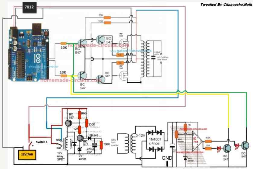
In the last article I have explained how to generate sine wave pulse width modulation or SPWM though Arduino, we are going to use the same Arduino board to make the proposed simple pure sine wave inverter circuit. The design is actually extremely straightforward, as shown in the following figure.
You just have to program the arduino board with the SPWM code as explained in the previous article, and hook it up with some of the external devices.
You may also want to read: H-Bridge Sine Wave Inverter Circuit
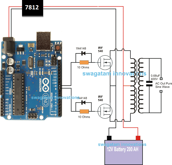
Pin#8 and pin#9 generate the SPWMs alternately and switch the relevant mosfets with the same SPWM pattern.
The mosfst in turn induce the transformer with high current SPWM waveform using the battery power, causing the secondary of the trafo to generate an identical waveform but at the mains AC level.
The proposed Arduino inverter circuit could be upgraded to any preferred higher wattage level, simply by upgrading the mosfets and the trafo rating accordingly, alternatively you can also convert this into a full bridge or an H-bridge sine wave inverter
Powering the Arduino Board
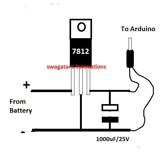
In the diagram the Arduino board could be seen supplied from a 7812 IC circuit, this could be built by wiring a standard 7812 IC in the following manner. The IC will ensure that the input to the Arduino never exceeds the 12V mark, although this might not be absolutely critical, unless the battery is rated over 18V.
If you have any questions regarding the above SPWM inverter circuit using a programmed Arduino, please feel free to ask them through your valuable comments.
Waveform Images for Arduino SPWM
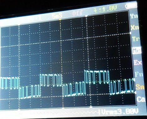
Image of SPWM waveform as obtained from the above Arduino inverter design (Tested and Submitted By Mr. Ainsworth Lynch)
UPDATE:
Using BJT Buffer Stage as Level Shifter
Since an Arduino board will produce a 5V output, it may not be an ideal value for driving mosfets directly.
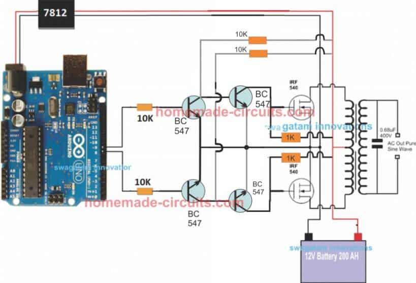
Therefore an intermediate BJT level shifter stage may be required for raising the gate level to 12V so that the mosfets are able to operate correctly without causing unnecessary heating up of the devices,. The updated diagram (recommended) can be witnessed below:
UPDATE: Get this Improved Arduino SPWM Code
Program Code for the above Arduino Sine Wave Inverter Circuit
// By Swagatam
void setup(){
pinMode(8, OUTPUT);
pinMode(9, OUTPUT);
}
void loop(){
digitalWrite(8, HIGH);
delayMicroseconds(500);
digitalWrite(8, LOW);
delayMicroseconds(500);
digitalWrite(8, HIGH);
delayMicroseconds(750);
digitalWrite(8, LOW);
delayMicroseconds(500);
digitalWrite(8, HIGH);
delayMicroseconds(1250);
digitalWrite(8, LOW);
delayMicroseconds(500);
digitalWrite(8, HIGH);
delayMicroseconds(2000);
digitalWrite(8, LOW);
delayMicroseconds(500);
digitalWrite(8, HIGH);
delayMicroseconds(1250);
digitalWrite(8, LOW);
delayMicroseconds(500);
digitalWrite(8, HIGH);
delayMicroseconds(750);
digitalWrite(8, LOW);
delayMicroseconds(500);
digitalWrite(8, HIGH);
delayMicroseconds(500);
digitalWrite(8, LOW);
//......
digitalWrite(9, HIGH);
delayMicroseconds(500);
digitalWrite(9, LOW);
delayMicroseconds(500);
digitalWrite(9, HIGH);
delayMicroseconds(750);
digitalWrite(9, LOW);
delayMicroseconds(500);
digitalWrite(9, HIGH);
delayMicroseconds(1250);
digitalWrite(9, LOW);
delayMicroseconds(500);
digitalWrite(9, HIGH);
delayMicroseconds(2000);
digitalWrite(9, LOW);
delayMicroseconds(500);
digitalWrite(9, HIGH);
delayMicroseconds(1250);
digitalWrite(9, LOW);
delayMicroseconds(500);
digitalWrite(9, HIGH);
delayMicroseconds(750);
digitalWrite(9, LOW);
delayMicroseconds(500);
digitalWrite(9, HIGH);
delayMicroseconds(500);
digitalWrite(9, LOW);
}
//-------------------------------------//
Video Clip
Parts List
All resistors are 1/4 watt, 5% CFR
- 10K = 4
- 1K = 2
- BC547 = 4nos
- Mosfets IRF540 = 2nos
- Arduino UNO = 1
- Transformer = 9-0-9V/220V/120V current as per requirement.
- Battery = 12V, Ah value as per requirement
Delay Effect
To ensure that the mosfet stages initiate with a delay during the Arduino booting or start up, you may modify left side BC547 transistors into delay ON stages, as shown below. This will safeguard the mosfets and prevent them from burning during power switch ON Arduino booting.
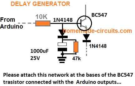
FOR INCREASING THE DELAY YOU CAN INCREASE THE 10K VALUE TO 100K
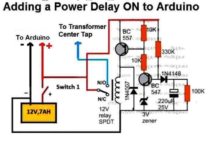
A More Reliable Delay ON Timer
If you are not comfortable with the response of the above passive delay ON timer circuit, you can employ the following configuration using BJTs and a relay. This design is extremely reliable and will effectively protect your Arduino and the inverter from burning due to a malfunctioning delay effect.
Just add this to the above inverter configuration.
Adding an Automatic Voltage Regulator
Just like any other inverter the output from this design can rise to unsafe limits when the battery is fully charged.
To control this an automatic voltage regulator could be employed as shown below.
The BC547 collectors should be connected to the bases of the left side BC547 pair, which are connected to the Arduino via 10K resistors.
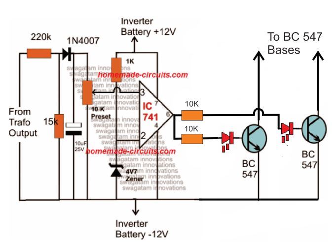
For an isolated version of voltage correction circuit we can modify the above circuit with a transformer, as shown below:
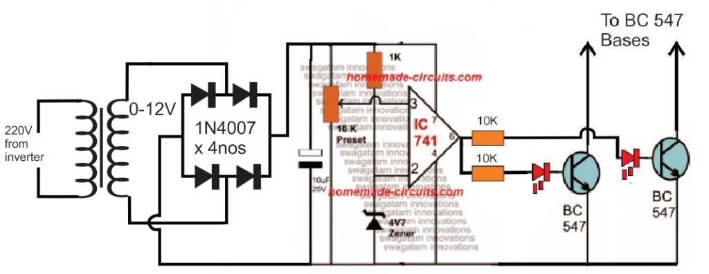
How to Setup
To set up the automatic voltage correction circuit, feed a stable 230V or 110V as per your inverter specs to the input side of the circuit.
Next, adjust the 10k preset carefully such that the red LEDs just light up. That's all, seal the preset and connect the circuit with the above Arduino board for implementing the intended automatic output voltage regulation.
The Complete Circuit Diagram
The complete diagram using the automatic voltage regulator and the delay ON timer would look like this:


at 12v input my output voltage is not going above 80-90volts . when I increased the input voltage around 30v my drain to source diode burned (i was using 4148 diode 😐 ) , can I use uf4007 as a flyback diode . I am using a push pull diver with pnp and npn for gate driving . I have used your gate driving method too , but my output never goes over 90volts . I have also tried a different transformer but same problem . not added the feedback circuit yet . can you help me please . I also tried using a 12v zener to protect the gate .
If you have used the second diagram with 4 BJTs, exactly as shown in the above article, then definitely it is the problem of your transformer.
Make sure the transformer primary is rated around 7-0-7V or 9-0-9V, and not 12-0-12V.
You can use freewheeling diodes across the transformer winding, between center tap and the outer taps. UF4007 is OK.
Please try with a 12v supply only, do not increase it.
sir thank you for the response . sir I have tried using a 9-0-9 transformer according to you but the results are same . can you please help me with this , I have to submit this projects within a week .
Akash, that means something may be wrong either with your transformer or your meter. I think you should test it with an oscilloscope.
As you can see everything worked perfectly for my prototype. The 100 watt bulb illuminated fully, without dropping any output voltage.
Are you testing it with an output load or without load? What is the Ah rating of your battery, and current ratings of your transformer?
sir without load i am getting 100volts and with load its dropping . I am using a 3ampere power supply . sir I have seen people using a higher ampere transformer . should I go for that ? or should I go for higher amp power supply ?
Akash, Please try the following design and let me know the results, if you still see the same problem, then certainly your transformer could be the culprit:
https://www.homemade-circuits.com/wp-content/uploads/2025/07/Arduino-sine-wave-inverter-circuit-using-TIP122-BJTs.jpg
Hi Bro
Thanks for sharing your experiences.
I’m really keen to know about 3 phases and the codes.
you mean 3 phases, but with how much votage?
110V or 380V
Thanks Bro, the voltage will depend on your choice, you can feed any desired DC voltage across the MOSFETs as per the load specifications…
1. anda menggunakan transformator jenis apa ? (inti besi, ferit, toroid) yang mana.
2. ideal waktu PWM berapa bagusnya ?
e-mail : fadhlyyy@yahoo.com
Iron core transformer is used in the above article.
For a ferrite core trafo you can use a pwm as high as 100kHz or above…
may you please explain the Arduino UNO code sir which used in it …….
Hello Anishka, you can refer to the following article for the full explanation:
https://www.homemade-circuits.com/arduino-spwm-generator-circuit/
sir maybe I supply Arduino from laptop ??
Yes, you can use the 5V from laptop USB to power your Arduino…
sir is that IRFZ44N mosfet use kar sakte ??
Yes, you can use IRFZ44 MOSFETs in the suggested design.
how to make spwm from 4 mosfet in place of 2 like shown in 1st fig upto 80-100W power (please show circuit diagram or DM at my E-MAIL ID)
Do you mean a 3 phase sine wave inverter using H-bridge topology?
Yes, I am planning to write an article on this topic.
I will post it soon and let you know.
No I’m actually talking about 1 phase with H bridge and it’s really helpful if you reply it or make an article on it …. plsI appreciate it if you do
OK got it! I will post it, and let you know soon..
Hi Sir im designing same project, i would really appreciate your assistance. I can even pay you if i have to. Please send me an email for update
Hi Walker,
No need to pay, if you have any related questions please feel free to ask, I will try my best to help you succeed with this project…
I’m Designing a transformerless inverter capable of delivering 500W and output frequency of 60Hz. Beside adding DC boost converter what other changes are to made if i follow steps of your project. It’s a pure sine wave inverter like yours.
No changes would be required in the H-bridge, you can build it exactly as shown.
Meaning i will have to add DC boost code to your code and my calculated DC boost values i will obtain pure sine wave inverter delivering 500W and AC output of 60Hz?
For bosting the battery voltage to a higher level at 60Hz, you only need to add a transformer at the output of the H-bridge MOSFETs, meaning the “LOAD” points must be replaced with the primary of the transformer, and the secondary can be used with an AC load with boosted output.
They were specific not to use a transformer that is why i chose to use DC boost converter
Then you can use the boosted DC output supply across the H-bridge MOSFET drain/source, that’s all is needed.
Sir if I make this project then it’s necessary that I need to use bread board?
And also if I wanna increase power output then I can use transformer?
And also sir is that I can use specific separate battery for supply Arduino UNO ?
Anishka, Breadboard is not recommended for the H-bridge project, so you should try it only on a well designed PCB.
If you are using a 12V battery, then you can use a transformer as the “load” for converting 12v to 220v.
Separate battery is not required.
You can use a IC 7812 for getting the 12V supply, and IC 7805 for getting the 5V supply for the circuits from the main 12V battery.
I have created the diagram which you can see below, while in the meantime I will write the article description on this.
https://www.homemade-circuits.com/wp-content/uploads/2025/03/arduino-sine-wave-full-bridge-inverter-circuit-diagram.jpg
For the code you can use the same code which was used in the above article…
thank you very much sir I appreciate it and it’s really helpful for me …
You are welcome Anishka,
For the complete article you can refer to the following post also:
https://www.homemade-circuits.com/arduino-h-bridge-sine-wave-inverter-circuit/
Witch is the maximum output power possible with IRF540 ? I need to obatain 100VA 110V @ 400 Hz for a vintage avionic radio equipment. Thanks.
100VA, 110V, 400Hz is easily achievable using IRF540 MOSFETs, provided the transformer and the battery are also appropriately rated.
Good day sir. can lm358 OpAmp be used for the feedback circuit?
Hi Hillary, yes any standard opamp can be used.
Hey I built this circuit today after some years now, I keep getting one Fet blown, not sure if its because I am using Irfz44n Fets, I did not build the delay on circuit, Instead switched pin 9 and 10 to input on boot up and added a delay then switch them to output when the arduino is fully booted after 2 seconds but I still have the same fet shorting on each leg, the software method is a standard practice, I I still get output from the inverter with one fet blown 30v.
Would irf740 work better thats the only other thing I have.
Hi, In my experiment I used IRF540 and did not have any such issues. But i don’t think the IRFZ44N can be the problem, unless the MOSFET has some internal defect. You can isolate the power supply input to the transformer center-tap and the Arduino, and then switch ON the Arduino first, and then after about 5 seconds switch ON the supply to the transformer and check the results.
irf740 may not be suitable because it is rated at 400V and your transformer may be rated at just 12-0-12V.
I added a software delay but when I read the article I realize the delay should just be for one Fet I delayed them both which is probably my issue.
also I used the modified spwm code that Mr Atton made im not sure if you tested that without issue also, if not I would just use your code.
Please initially check with a manual delay, by isolating the transformer center tap and the Arduino, and please use only the code supplied by me, because it is the tested one.
Hi swagatam. Trust you good?. I have designed the above circuit which is working perfectly fine. But my problem is the feedback circuit which I have designed just as it is but it is still not working. Please try and solve my problem for me. Thanks
Thank you Jonathan,
I hope you have built and implemented the following feedback circuit:
https://www.homemade-circuits.com/wp-content/uploads/2019/03/Arduino-regulation.jpg
I would suggest you to test this circuit stage separately using a variac.
In this circuit, can you please test how much voltage do you get across the 10uF capacitor.
Remember, this DC voltage across the 10uF is the direct interpretation of the AC 220V that comes from the inverter output. When the inverter output voltage rises, this DCV also rises. As soon as this corresponding DC voltage at pin#3 of the 741 IC goes above the pin#2 zener vooltage, the output pin#6 of the IC turns high causing the BC547 to conduct and ground the MOSFET gates, shutting down the inverter.
So please verify the above stage separately and let me know.
Hi Swagatam,
As you know, sinewave PWM (SPWM) could be generated at different high frequencies (though much higher than 50 Hz). Since I don’t have Arduino board (though I design the hardware and firmware of my controllers using AVR MCUs, as ATmega8 and ATmega32) I wonder if you measured the PWM frequency which is generated by the offered Arduino firmware above. Thank you.
For instance, let us assume that the SPWM frequency is around 16 KHz. Naturally, it needs to be filtered to generate the 50Hz pure sinewave output at the transformer secondary. I read many articles on how to build a pure sinewave inverter, but none of them shows how the SPWM filtration is done. The only device which is supposed to do it in their circuits is the inverter power transformer since there is no explicit filter. But to let the transformer act as a filter, its mutual coupling coefficient (K) shouldn’t be made close 1 (as in mains stabilizers for example). The more K is made lower than 1, the higher the leakage inductance between the MOSFETs and the load is. And this leakage inductance does the filtering (shunted also by the iron losses at the high frequencies). But the more (K) is made lower than 1, the lower the transformer efficiency is. In practice, separating the coils of the primary and secondary, instead of winding them on the same coil, lowers (K). The optimum distance between the two coils is usually determined by trial and error. But if by adding a small capacitor (<1uF) at the transformer output (not loaded), the output voltage is acceptable (its high frequency ripple is hardly noticeable), the transformer is ok.
Thank you Kerim, for the valuable information.
Each 50 Hz half cycle is chopped into 7 pillars, or 7 pieces, so each 20 millisecond cycle accompanies 14 PWM peaks.
I know this may look a little higher to handle for an iron core transformer, but in my experiment it worked perfectly well, without any buzzing or heating up of the transformer.
Yes, adding a high voltage capacitor at the output side of the transformer helps to smoothen the SPWM cycles into pure a sinewave like frequency.
If I understood you well, the PWM of the Arduino program (above) is 700 Hz only. At this relatively low frequency, I expect the ripple of the sinewave output is not small. So, I wonder how it looks on your scope screen in your experiment. Please let me know if the output ripple could be made small even at this very low PWM frequency and without an external LC filter. Thank you.
But, even with such a high ripple, the generated output is much better than of a square wave or quasi-sinewave.
For instance, among your many published articles about the pure sinewave inverters, which one its PWM frequency is highest?
Thank you Kerim, for calculating the frequency.
According to my knowledge the only way to reduce the ripple is either by using a capacitor at the transformer output or by increasing the pwm frequency and using a ferrite core transformer.
In the above Arduino concept I used a 3uf capacitor at the output which produced a relatively good sinewave, however if this capacitor value is increased that might further help to improve the sine waveform quality and reduce the ripples proportionately, although that would also incur some power wastage. The above sinewave inverter project uses the maximum frequency for the pwm among all the published articles.
I asked about the SPWM frequency because lately I wrote a code for ATmega8 to generate the SPWM at 15.625 KHz (8000 KHz / 512). (For instance, since about 40 years ago, I used to write my CPU/MCU codes in assembly language only). This code can be used for a push-pull inverter which I designed its hardware too. Its push-pull transformer could be driven by two sets of N-MOSFET which, in turn, are driven by discrete circuits using BJT; NPN & PNP for fast turn on-off with dead time.
By simulating the code and its hardware, the results were as expected. I set K=0.99 in the transformer model. I hope soon I will have the time to test it in real.
In case we will find a way to let you receive files from me, I don’t mind sharing my design here (code and circuit).
MCUs existed 40 years ago? I did not know that. Thanks for sharing the info.
Sure, please feel free to share the codes anyway you like, through email or directly through comments using online free upload sites.
I appreciate your kind efforts.
Sorry for not being clearer. You are right, 40 years ago, MCUs didn’t exist, only CPUs did (as Z80).
I had to say on my precious post:
“In the last 40 years, I used to write first my CPU codes (for Z80), then my MCU codes (for C51 and AVR families).in assembly language only”.
OK, got it, thanks for the clarification.
Few suggestions:
– Can the delay circuit be realized mainly in the software? I think the Arduino microcontroller ensures that on power on, all I/O pins are set to the input direction and in the high-Z mode by the microcontroller electronics. Software must explicitly configure pins for output or PWM. Suppose the Arduino pins that drive BC547 transistors are pulled to the ground with 100k or stronger resistors. Would it be enough to ensure that the MOSFET stages initiate with a delay during the Arduino booting or start-up? MOSFETS will be active once the Arduino application reconfigures the pins driving BC547 transistors.
– The automatic voltage regulator can be realized mostly in the software. Arduino has 6 ADC inputs and is capable of performing tens of thousands of ADC conversions a second. A simple voltage divider with a diode and capacitor as a half-wave rectifier can be connected to the Arduino ADC pin. Arduino ADC pins have about 100k input impedance, so a half-wave rectifier should be good enough. After every SPWM cycle, Arduino can read the output voltage and decide what to do next.
Thank you for your valuable suggestions, it would be indeed very nice if the delay feature and the automatic voltage control are added within the Arduino. Please let us know if you have the necessary programming codes for that.
Yes, if the Arduino pins that drive BC547 transistors are pulled to the ground with 100k or stronger resistors, that would be enough to ensure that the MOSFET stages initiate with a delay during the Arduino booting or start-up.
Would I only need to pull one side to ground or both bc547
both the BJTs….
how can I make closed loop single phase inverter using Arduino
Please go through the above article, everything is explained in it.
Hello sir I want to control inverter out put by varying the the duty cycle values of arduino by push button from 0 to 100% duty cycle at increment or decrement by 1%.
I want to make 0 to 10 volt pure sinwave inverter at 400 Hz frequency and the ac voltage can be controlled by microcontroller at +/- 1% duty cycle variation so that 10 volt AC change accordingly.
Thanks and regards.
Please suggest me the code and circuit.
Hello RK, I wish I could solve your query, however my Arduino coding skills are not good enough, therefore it can be difficult for me to help you with this question.
thanks for reply.
So the CMOS based circuit seams like an inherently better circuit as circuit loading does not affect the arduino outputs? however, I notice there is no feedback mechanism like it the upper circuit. Is it not possible or just not needed because of the buffer?
There’s no loading with the transistorized circuit also due to the presence of the 10K resistors. 10K is quite a high value and will absolutely not cause any loading on the Arduino.
Yes, feedback might not be necessary since the Arduino generates a fixed PWM.
then which circuit would you choose? I am planning to build a low powered 12V, 500ma, to 120V variable frequency inverter.
Also, I have started trying to source components for the CMOS version but find that at Digikey many items are either obsolete or require purchasing large quantities, I’m not willing to pay $3000 to use only 2 transistors. Can you suggest alternate parts?
The transistorized version of the above Arduino inverter is the most efficient one and is a tested design. I would recommened this design. The 10K resistor associated with the Arduino outputs can be even raised to 100K to reduce loading.
I did not quite understand what you meant by “I’m not willing to pay $3000 to use only 2 transistors. Can you suggest alternate parts?” Kindly elaborate
BC547 is listed as obsolete on Digikey. https://www.digikey.com/en/products/detail/onsemi/BC547/976363#product-details-substitutes
BC548 is also obsolete in bulk, but i I buy 6662 of them they are only .05 each. ($333.10) , https://www.digikey.com/en/products/detail/rochester-electronics-llc/BC548/11545848
i forget which one only had a $3000 option. i’ll have to take better notes in my searching
That’s super strange because BC547 is the most standard type of BJT and one of the most used general purpose transistor…. how on earth this transistor can become obsolete??
You can try 2N2222 or any other equivalent transistor, they all will work.
couple more questions about the Voltage regulator circuit.
1) what is a 4V7 zener? 4V, 7V 4.7V? or other?
2) there are 2 led’s shown in series with the gates on BC547. are they required? this will be in a box and used remotely. do they have a troubleshooting purpose?
1) 4V7 = 4.7V
2) Yes they are required, since the LEDs prevent the leakage or the offset voltage from 741 output to reach the base of the BC547 transistors, thus preventing false switching of the transistors..
are they just standard 12V(forward Voltage) Red LED’s?
They are standard 3.3 V, 20 mA LEDs.
one more question about the voltage regulator, is this what you mean by IC741?
https://www.digikey.com/en/products/detail/texas-instruments/TPIC74100QPWPRQ1/1531097
if so, is there a through hole substitute?
741 is an IC, not a voltage regulator, if you are not familiar with 741 IC then I am afraid you should not try this circuit, chances are you might not succeed.
https://www.homemade-circuits.com/wp-content/uploads/2021/08/IC-741-and-LM393-comparison-compressed.jpg
Sorry, I did not recognize the Op-Amp symbol. The regulator I found is Also an IC. Searching on Both digikey and Mouser for IC741 resulted in nothing, so I went the hard way (drilling down) and had to choose a category. Voltage Regulator was just a guess. The wiring for the OP-Amp seams straight forward (other than the LED’s,) and i plan to use a socket so as to not damage the Chip when soldering, so i’ll take my chances. I’m just an electrician with electronics hobby experience not an electronics engineer. Sorry for the dumb questions, but I need this Arduino controlled inverter for one of my other hobbys (Astrophotography) .
No problem, you can go ahead and build this project. The op amp output voltage control might not be necessary since the Arduino is generating a calculated fixed PWM, so the output voltage should be pretty constant.
sir, how to construct a 450w 12vdc-230vac solar inverter?
Aqil,
Please provide detailed information regarding the inverter and the load, if possible I will try to help.
A 12V solar panel and 12V battery supply to a 350W water filter. All i need is 500W (inverter sizing) inverter circuit diagram with code
If you divide 350 by 12, it gives 30 amps, so your transformer must be rated at 6-0-6 30 amps or 32 amps. Please get this transformer then I will tell you how to proceed.
i dont find for step up transformer. i just found for step down transformer…
Step down transformer will do but it must rated at 6-0-6V 32 amps on one side and 220V on the other side.
Okay now proceed to the next step sir
Did you get the transformer?
Yes
Please build the circuit which is explained above using that transformer. You will also need a 12V 300 Ah battery for the 350 watt output
Hello sir, thank you for the Arduino sine wave circuit, can the circuit also be used for 24V DC?
Thank you Emmanuel,
24 V can be also used. For that you will need a 12-0-12V transformer and the +24V will need to be fed on its center tap. The Arduino must be fed with 12 V through a 7812 IC.