Here we are going to learn one cool and very important current sensor device which we call ACS712. This small chip that look just like a normal 8-pin IC, is actually able to sense current from any load and give us a proportional analog voltage output which we can easily feed to Arduino or any microcontroller ADC pin. So now, using this one, we can measure current for both AC and DC very easily, but with right precautions, ok.
What Exactly is ACS712?
So ACS712 is a hall effect based current sensing IC which means it uses a magnetic field around the wire or track to detect the current and then that magnetic field is converted to voltage signal using internal hall element inside the chip. So the best thing is that the chip is completely electrically isolated from load side which makes it very safe and reliable.
Main Features and Specs of ACS712 (Table)
| Parameter | Details |
|---|---|
| Supply Voltage (Vcc) | 5V DC |
| Output Type | Analog Voltage |
| Sensing Type | Hall Effect |
| Measurement Range (varies) | ±5A, ±20A, ±30A versions available |
| Output Sensitivity (typical) | 185 mV/A (for 5A), 100 mV/A (20A), 66 mV/A (30A) |
| Bandwidth | 80 kHz |
| Response Time | 5 µs |
| Internal Resistance (path) | 1.2 mΩ (approx.) |
| Operating Temperature Range | -40°C to +85°C |
So here we can see that, we get 3 versions: 5 Amp, 20 Amp and 30 Amp. But all have same kind of output, which is analog voltage signal that varies depending on current level.
Pinout Details
Let us understand the pinout of ACS712 so that we can wire it correctly:
| Pin No. | Name | Function |
|---|---|---|
| 1 & 2 | IP+ | Current Input Positive terminal (Load +) |
| 3 & 4 | IP- | Current Input Negative terminal (Load -) |
| 5 | GND | Ground (connect to Arduino or 0V of circuit) |
| 6 | FILTER | External capacitor can be added to reduce noise |
| 7 | VOUT | Analog Output Voltage (connect to ADC pin) |
| 8 | VCC | +5V Supply |
How It Works
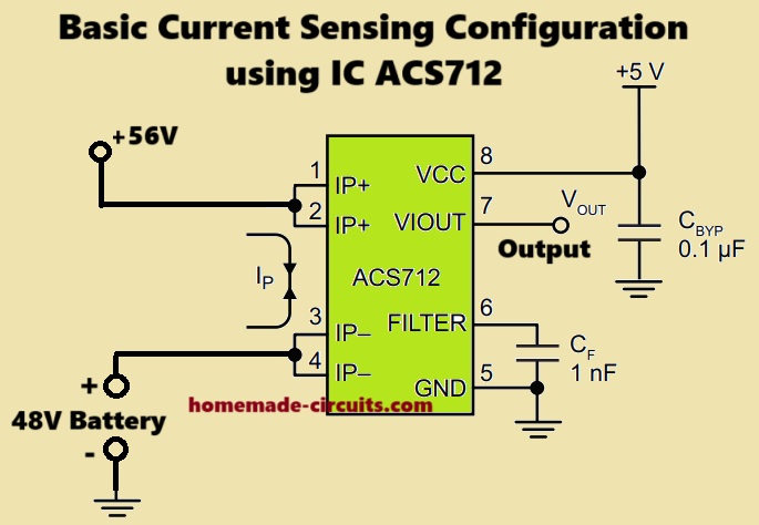
So now, let us imagine we want to measure current of a motor or a bulb. We just pass the supply line through the ACS712 sensor terminals (IP+ and IP-).
This current creates magnetic field in the hall sensing area and the chip quickly converts that magnetic flux into a proportional analog voltage which we get at the VOUT pin. This voltage will be higher or lower depending on how much current is flowing.
Now when there is no current, the VOUT sits exactly at Vcc/2 = 2.5V which is like zero current reference. If current flows in one direction, then voltage goes higher than 2.5V, if current goes in reverse direction (like in AC or bidirectional DC), then voltage drops below 2.5V.
Output Voltage Formula
So, if we want to calculate current from output voltage, then we can use:
Current (Amp) = (Vout - 2.5) / Sensitivity
Where:
- Vout is the voltage read from the output pin.
- 2.5V is the zero current level.
- Sensitivity depends on module:
- 5A module = 185 mV/A.
- 20A module = 100 mV/A.
- 30A module = 66 mV/A.
So for example if we use 20A module and Vout = 3.0V, then:
Current = (3.0 - 2.5) / 0.1 = 5A
Arduino Wiring and Example Code (For 20A Module)
Let us wire it with Arduino now:
Connections:
- Vcc → Arduino 5V
- GND → Arduino GND
- Vout → A0 (Analog input)
- IP+ and IP- → In series with the load line
Circuit Diagram to Read Load Current of Computer Screen

Sample Arduino Code:
int sensorPin = A0;
float voltage = 0;
float current = 0;

void setup() {
  Serial.begin(9600);
}

void loop() {
  int value = analogRead(sensorPin);
  voltage = (value * 5.0) / 1023.0;
  current = (voltage - 2.5) / 0.1;  // for 20A version

  Serial.print("Current: ");
  Serial.print(current);
  Serial.println(" A");

  delay(500);
}
Things We Must Take Care
- Noise filtering: Use a capacitor (say 0.1uF) across FILTER pin and GND to reduce noise.
- Stable Vcc: Use only 5V regulated supply, otherwise readings will become wrong.
- No wrong polarity: Don’t reverse IP+ and IP-, or it can give reverse readings.
- Do not cross rated current: If you use 5A module then do not pass more than 5A.
Maximum Tolerable Voltage across IP+ / IP– Terminals (Current Path)
| ACS712 Version | Max Rated Current | Internal Resistance | Max Recommended Voltage Drop | Approx Max Voltage Drop Between IP+ and IP– |
|---|---|---|---|---|
| ACS712-05B | ±5 Amps | 0.185 Ohm | ~0.185 × 5 = 0.925V | Less than 1V |
| ACS712-20A | ±20 Amps | 0.066 Ohm | ~0.066 × 20 = 1.32V | Around 1.3V max |
| ACS712-30A | ±30 Amps | 0.033 Ohm | ~0.033 × 30 = 0.99V | Less than 1V |
Important Warning:
- You CANNOT apply mains AC (like 220V or 110V) directly across IP+ and IP–. That will instantly damage the chip or create deadly shock risk.
- Even with a series load, these IP terminals are NOT isolated from VCC/GND inside the module. They are floating on the same ground (not transformer-isolated) so high voltage on IP side will also come to signal side.
What is Safe to Apply:
- You must pass only low-voltage current-carrying wires through the IP side.
- For example, you can place it in series with:
- 12V DC motor wire or
- 24V battery line or
- Solar panel line (under 50V is OK)
- Max common-mode voltage on IP side = around 100V peak max (as per Allegro datasheet), but module form may reduce that to 60V for safety.
Advantages
The main advantages of this IC are listed as shown below:
- Fully isolated and safe.
- Works for AC and DC both.
- Easy analog output, no complex interface.
- Compact size.
- Cheap and available.
Limitations
There are some limitations of this IC, which are as follows:
- Sensitivity fixed, cannot be changed.
- Output is not digital, so needs analog pin.
- Small offset errors possible.
- Cannot handle more than rated current.
Applications of ACS712
This IC can be used in the following applications:
- Overcurrent protection circuits.
- Battery charger current monitor.
- Inverter current feedback.
- Motor load monitoring.
- Solar power tracking.
- General current measurement tools.
Conclusion
So this is how we can use ACS712 current sensor IC to build our own current meter or protection circuit or current based auto cutoff system. It is small, simple and it works very accurately if we handle it properly. But always remember never try to pass more current than rated value.
Application Circuits
Now let us see how we can apply the IC ACS712 into practical circuits for measuring or sensing current trigger a corresponding output load when the threshold cut off current is detected.
1) Over Current Load Cut-off Protection using Arduino and ACS712
You want to make an overcurrent protection system using ACS712, where:
- The relay turns ON permanently (or cuts power permanently) if current goes above a certain limit
- The system must not auto-reset even if the current drops later
- It should only reset when power is manually switched OFF and ON
This is a classic latching trip system like a self-hold. And yes this can be done very easily with Arduino.
What we need to do
So now we will:
- Read current from ACS712 as usual.
- Set a current limit (like 5A or whatever you need).
- Add a flag that latches when trip happens.
- After that, even if current drops, then also flag stays active.
- Arduino will not reset the flag unless power is cut and restarted.
Because variables like trip = true get cleared automatically when Arduino resets due to power OFF–ON, the trip will also reset automatically when user power cycles.
Circuit Diagram for the Over Current relay Load Cut-off using ACS712 and Arduino

Arduino Code
int sensorPin = A0;
int relayPin = 8;

float voltage = 0;
float current = 0;
float threshold = 5.0;  // trip limit in Amps (set as needed)

bool tripped = false;  // latch flag

void setup() {
  Serial.begin(9600);
  pinMode(relayPin, OUTPUT);
  digitalWrite(relayPin, LOW); // Keep relay OFF initially
}

void loop() {
  if (!tripped) {
    int value = analogRead(sensorPin);
    voltage = (value * 5.0) / 1023.0;
    current = (voltage - 2.5) / 0.1;  // for ACS712 20A version

    Serial.print("Current: ");
    Serial.print(current);
    Serial.println(" A");

    if (current > threshold) {
      digitalWrite(relayPin, HIGH);  // Trigger relay
      tripped = true;                // Latch the trip
      Serial.println("Overcurrent detected! Relay latched ON.");
    }
  }

  delay(500);
}
How it works
So now we will see how this overcurrent protection program is working inside Arduino in step-by-step simple explanation. When the Arduino is switched ON, then at that time we are making one flag called tripped which we are setting to false. That means system is not tripped yet and everything is normal.
So now Arduino will go inside the loop and it will keep reading the analog input from the ACS712 sensor again and again. It reads the voltage and then calculates the current flowing from that sensor. After that it will compare the calculated current with the threshold value which we have already fixed in the program. For example, that can be 5 amps or 10 amps or whatever we want.
So then when the current becomes more than that threshold value, then at that moment the Arduino will activate the relay by giving HIGH signal to the output pin. And after doing that it will also make the tripped flag as true. That means Arduino now remembers that trip has already happened and system is now in trip mode.
So then once this tripped flag becomes true, after that the Arduino will not read the sensor again. It will skip that part. That means the current value can go high or low later but Arduino will not check anymore because we already entered trip condition. That is how we are stopping the program from resetting automatically.
So now the relay will stay permanently ON and nothing will change even when current comes back to safe level. That trip will remain active until we manually switch OFF the Arduino power and then turn it ON again.
That power cycle will clear the tripped variable and again system will come back to normal mode. So this is how we are making one permanent latching type protection system using very simple code.
How to connect relay module and ASC712 (in our crude style)
So now we will also see how to connect the ACS712 current sensor and the relay module with Arduino board step-by-step. First we will do sensor wiring.
ACS712 wiring explanation
This sensor has three pins which are Vcc, GND and Vout.
We have to connect the Vcc pin of the sensor to the 5V output of the Arduino board. That will give power to the sensor module.
Then we connect the GND pin of the sensor to the GND pin of Arduino so that both are sharing common ground.
After that we connect the Vout pin of the sensor to the A0 analog pin of Arduino because from here Arduino will read the voltage and calculate current.
Relay module wiring explanation
Now for the relay module, we also have three pins. Those are Vcc, GND and IN.
We connect the Vcc of the relay module to 5V of Arduino just like sensor.
Then we connect the GND of relay to GND of Arduino again to keep ground same.
Now we connect the IN pin of the relay to Arduino pin D8 because we are controlling the relay using that pin in the program.
Output connection for load or charger
Now the relay module will have output terminals which are called NO (normally open), NC (normally closed) and COM (common). So we will use COM and NO terminal to connect our actual load like charger or device.
We connect one wire from battery or input to COM and then connect the NO to the positive line of the load. This way the load will receive power only when relay is activated.
That's it!
2) Peak Detecting Circuit: What this circuit do?
It senses current from AC (or DC), and gives a steady DC voltage at the output which tells you the highest peak of the current wave. So even if current is rising and falling, this thing will grab the topmost level and hold it until you manually reset it.

Let’s understand stage by stage:
ACS712 Current Sensor Block
- IP+ and IP– (Pins 1 and 2): These are the current-carrying path. Your AC or DC load goes through this.
- Inside the chip, a hall sensor reads the magnetic field generated by this current.
- VIOUT (Pin 7): This pin gives a voltage proportional to the current. Mid value is 2.5V for 0 amps. Goes up or down depending on direction of current.
- FILTER (Pin 6): You can add a capacitor here to smooth the signal.
- VCC (Pin 8): You give 5V power here.
- GND (Pin 5): Ground.
- CBYP (0.1uF): This is just a power supply bypass cap to stop noise on the 5V line.
Signal Conditioning Section
This section prepares the ACS712 output (VIOUT) and sends it to a precision op-amp for peak detection.
- COUT (0.1uF): AC coupling cap – blocks DC, passes only AC variation.
- RF (10k), R1 (1M), CF (1nF): These are around the op-amp to make a precision peak detector with fast response and filtering.
So here, the op-amp is configured to track only the rising edge of the waveform and charge the cap (C1) to match the peak level.
Op-Amp + Diode Peak Detection
- U1 (LT1178): This op-amp compares VIOUT signal and charges C1 (0.1uF) through D1 (1N914).
- D1: Allows current only when op-amp output is higher than C1 voltage. So it will charge C1 with peak value.
- R3 (330k): Discharge path of C1, but very slow (so value is held long time).
- R2 (33k): Ground reference for the op-amp.
MOSFET Reset Stage
- Q1 (2N7002): N-channel MOSFET. It’s like a switch.
- C2 (0.1uF), R4 (10k): Smooth out any glitch in the reset pulse.
- When you pull VRESET high, this MOSFET turns ON and short circuits C1 to ground.
- So C1 discharges, then output peak resets to zero, then it is ready to catch next peak.
Output
- VPEAK: This is the final DC output.
- It holds the highest peak level of the current waveform until you reset it using VRESET.
3) ACS712 Output Amplifier Circuit
This one is amplifying the output of ACS712 using a non-inverting op-amp (LM321). So instead of the regular 185 mV/A (for 5A version), we now get 610 mV/A, much bigger swing = better resolution.
Good when you want to read small current changes more clearly using a voltmeter, Arduino, etc.

ACS712 Current Sensor stage working will be the same as explained in the above section.
Non-Inverting Op-Amp Gain Stage
- Op-amp = LM321, powered by 5V single supply.
- Configured as non-inverting amplifier using resistor divider and feedback:
- R1 = 100k, R2 = 100k
- This forms a reference voltage divider, giving 2.5V at op-amp non-inverting input (+).
So even when signal is AC, op-amp sees a center point at 2.5V → helps for single-supply work. - RF = 1k, R3 = 3.3k → These set the gain of the amplifier.
- Gain formula = 1 + R3 / RF = 1 + 3.3k / 1k = 4.3 times
- So original ACS712 140 mV/A × 4.3 = around 610 mV/A now.
Output Smoothing
- Output goes to C1 (1000pF) for final filtering to remove any ripple or sudden jump.
Final Output (VOUT)
- This is the final amplified signal.
- So now:
- When current is 0A → VOUT will be 2.5V (midpoint)
- For +1A → VOUT rises to ≈ 2.5V + 0.610V = 3.11V
- For -1A → VOUT drops to ≈ 2.5V – 0.610V = 1.89V
- Means for every ampere, output swings by 610 millivolts. Much easier to detect using ADC or even voltmeter.
In simple words, this circuit is doing one job, it takes the weak output from ACS712 and boosts it using an op-amp, so we can get a stronger signal per amp. This is useful when you are sensing small current, and want more voltage change to detect that clearly.
It uses op-amp in non-inverting mode with voltage divider to fix center bias at 2.5V and gain set using feedback resistor. Final output gives you a loud, clear, and amplified version of what ACS712 is saying.
4) Analogue to Digital Converter
What this circuit is doing?
This one is trying to catch the peak current coming from ACS712 and send that peak value to an ADC (Analog to Digital Converter). So, instead of sending a full AC waveform, we only give the highest point, like a peak-hold meter.

It is like saying: “Look dont give me the full up-down signal, just give me the highest level reached.”
ACS712 Current Sensor (same basics)
- Pins 1 and 2 (IP+ and IP–) = Here we connect the AC or DC current path. Whatever current is flowing through your wire, it will go through this internal shunt inside the IC.
- It generates a voltage on VIOUT (pin 7) which is:
- 2.5V if current is zero
- Goes higher or lower depending on current direction
- CBYP = 0.1uF across VCC to GND → helps to keep power line clean.
- CF = 1nF across pin 6 (FILTER) and GND → smoothes out signal, stops high frequency ripple.
- RF = 2k, R1 = 10k form a simple passive filter and resistor bridge for stability, bandwidth shaping.
Peak Detection Section
Now the interesting part:
VIOUT goes through:
- RF (2k) → limits current into the next diode
- Then goes to D1 (1N4448W) → this is a fast diode, and acts like a one-way gate.
- When voltage from ACS712 increases, this diode allows it to charge capacitor C1 (the big hero here).
- When voltage drops, diode blocks the path. So the C1 keeps the last highest voltage stored.
So this combo of diode + capacitor C1 acts like a peak holder or sample-and-hold circuit.
That means that if current increases then voltage rises and so C1 charges.
If current decreases then the diode blocks, and capacitor keeps its last peak voltage.
This voltage can then be read by an ADC, like Arduino or microcontroller.
Final Output to A-to-D Converter
- The voltage on C1 is directly connected to the ADC input.
- That ADC reads only the highest peak voltage that occurred during the time interval.
If you want to reset this voltage, you can add a switch across C1 (or use a transistor to discharge C1) but that is not shown here.
Why this circuit is useful?
When you want to measure peak current, like motor surge, or AC wave top value.
When your microcontroller is too slow to catch fast up-down signal but can read a held voltage.
Very useful in AC current monitoring or overload detection.
Final Word:
this circuit is working like a peak voltage trap. It catches the biggest voltage that came out of ACS712 and holds it on capacitor using a fast diode. After that, then microcontroller or Arduino can read this held voltage using ADC. This way, we do not lose fast spikes or peaks in current.
Overcurrent Fault Latch Circuit
What this circuit is doing?
This one is called overcurrent fault latch circuit. That means: if the current goes above a set limit then circuit will lock the fault and will not release even if current comes back to normal. Only way to reset it is to turn OFF and ON the 5V supply again.

ACS712 Part (same as usual)
- IP+ and IP− = pin 1 & 2 → here your load current flows.
- Pin 7 (VIOUT) = gives out analog voltage proportional to current.
- 2.5V when current is 0A
- Goes up/down depending on current direction.
- Pin 6 (FILTER) has a 1nF capacitor to GND which filters noise.
- Pin 8 (VCC) = connected to +5V, Pin 5 (GND) = ground
- CBYP 0.1uF = power supply decoupling capacitor to stop ripples.
So till now, ACS712 is measuring current and giving analog signal at pin 7.
Setting the Fault Threshold
This is the most important part:
- R1 = 33k, R2 = 100k → these two form a voltage divider from 5V to GND.
- This divider creates a reference voltage on the non-inverting pin (+) of the comparator U1 (LMV7235).
- This sets our fault threshold.
- For example, this might be around 1.3V to 2.0V depending on the divider.
Comparator U1 (LMV7235)
- This IC is a comparator. It compares two voltages:
- VIOUT from ACS712 on inverting pin (−).
- Threshold voltage from divider on non-inverting pin (+).
If VIOUT is less than threshold → output is HIGH (no fault).
If VIOUT crosses the threshold → output becomes LOW → fault triggered.
Latching the Fault (Holding it forever)
Here comes the magic:
- When output (pin 1 of comparator) goes LOW (fault), diode D1 (1N914) feeds this LOW signal back to the non-inverting (+) input.
- That means the threshold voltage gets pulled LOW, and the comparator sees:
- "Oh! Now threshold is also low, I cant go back to normal anymore."
So this creates a latch. Once fault triggers then it keeps itself in fault mode even if current drops.
This is called positive feedback through diode = Latching action.
Only way to clear this latch is:
cut the 5V power and give it again. Then the fault will reset.
Final Output
- The “FAULT” signal is taken from comparator output.
- There’s a pull-up resistor RPU = 100k to keep the signal HIGH when no fault.
- When comparator pulls LOW then FAULT becomes active (LOW state = fault detected).
You can connect this FAULT pin to a microcontroller, buzzer, relay driver, etc.
Practical Use Case:
- This is like a protection system.
- Used in battery chargers, power supply, motor drivers, where we don’t want to keep retrying after overcurrent.
- Instead we say:
“hey, fault happened, stop everything and wait until user resets me.”
Final Conclusion
This circuit is like a watchdog for current. If the load current goes too high, then voltage from ACS712 also goes high.
Comparator catches that and says ‘fault!’ by pulling the output LOW. Then it tricks itself and stays locked in fault by using the diode.
Even if current goes back to normal, the circuit says ‘nope, still fault’. Only way to reset = shut off 5V and restart. Very safe system to catch overcurrent once and freeze it until full reset.
Source: ACS712 datasheet


Comments
excelent explations