• Skip to main content
  • Skip to primary sidebar

Homemade Circuit Projects

Need circuit help? Post them in the comments! I've answered over 50,000!

Blog | Categories | About | Contact | Calculators-online

Home - Datasheets and Components - TIP122 Datasheet [100V, 5 amp, NPN, Darlington Transistor]

TIP122 Datasheet [100V, 5 amp, NPN, Darlington Transistor]

Last Updated on February 23, 2023 by Swagatam Leave a Comment

The TIP122 is an NPN Darlington pair transistor that is commonly used in power switching applications. It has a high current gain and can handle up to 5A of continuous current.

Table of Contents
  • Electrical Characteristics (Do not exceed these specifications):
  • Package Type:
  • Pin Configuration:
  • Applications:
  • Simplest Solar Charger Application Circuit

Here is the complete datasheet for the TIP122 transistor:

Electrical Characteristics (Do not exceed these specifications):

  • Collector-Base Voltage (VCBO): 100V
  • Collector-Emitter Voltage (VCEO): 100V
  • Emitter-Base Voltage (VEBO): 5V
  • Collector Current (IC): 5A
  • Base Current (IB): 5A
  • Power Dissipation (PD): 65W
  • DC Current Gain (hFE): 1000 (min) at IC=3A, VCE=4V
  • Switching Speed: 3MHz (typical)

Package Type:

The TIP122 transistor is available in a TO-220 package, which is a standard three-lead package with a metal tab for heat dissipation.
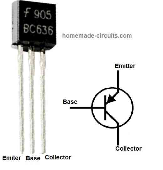
Pin Configuration:

As shown in the diagram, the TIP122 transistor has the following three pins:
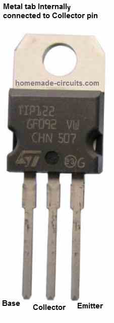
TIP122 pinouts
  • Pin 1: Base
  • Pin 2: Collector
  • Pin 3: Emitter

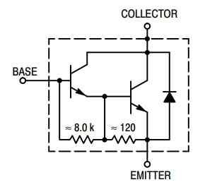
The internal Darlington configuration of the transistor is as shown below:

TIP122 internal Darlington configuration

Applications:

The TIP122 transistor is commonly used in power switching applications such as:

  • DC motor control
  • Solenoid control
  • Lamp control
  • Relay control

Simplest Solar Charger Application Circuit

The following image shows how TIP122 transistor can be used to build a simplest solar charger circuit:

TIP122 simplest 12V battery charger circuit

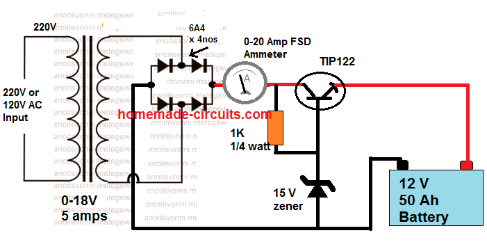
The output voltage is calculated using the following formula:

Vout = zener value - TIP122 forward drop

= 15 - 1 = 14 V

The TIP122 here is configured as an emitter follower, therefore its forward voltage drop will be approximately equal to 0.6 + 0.6 = 1.2 V. The double 0.6 V is due to the Darlington transistor, each dropping around 0.6 V.

Note: This datasheet is for reference only. Please refer to the manufacturer's datasheet for complete specifications and characteristics of the device.

You'll also like:

  • 1.  EGS002 Datasheet, Circuit Diagram Explained
  • 2.  Understanding Color Codes of Resistors with Practical Examples
  • 3.  IC 4040 Datasheet, Pinout, Application
  • 4.  IC 4024 Datasheet, Pinout Working, Application Circuit
  • 5.  OBD2 Connector Pinout, Datasheet
  • 6.  Comparator Datasheet Parameters

About Swagatam

I am an electronics engineer with over 15 years of hands-on experience. I am passionate about inventing, designing electronic circuits and PCBs, and helping hobbyists bring their projects to life. That is why I founded homemade-circuits.com, a website where I share innovative circuit ideas and tutorials. Have a circuit related question? Leave a comment.... I guarantee a reply!

Previous Post: « IC 4011 Datasheet, Pinout, Applications
Next Post: How to Connect Resistors in Series and Parallel »

Reader Interactions

Need Help? Please Leave a Comment! We value your input—Kindly keep it relevant to the above topic! Cancel reply

Your email address will not be published. Required fields are marked *

Primary Sidebar


Subscribe to New Circuits

Categories

  • Arduino Projects (87)
  • Audio and Amplifier Projects (132)
  • Automation Projects (17)
  • Automobile Electronics (101)
  • Battery Charger Circuits (83)
  • Datasheets and Components (104)
  • Electronics Theory (143)
  • Free Energy (37)
  • Games and Sports Projects (11)
  • Grid and 3-Phase (19)
  • Health related Projects (25)
  • Home Electrical Circuits (12)
  • Indicator Circuits (14)
  • Inverter Circuits (87)
  • Lamps and Lights (142)
  • Meters and Testers (69)
  • Mini Projects (46)
  • Motor Controller (64)
  • Oscillator Circuits (27)
  • Pets and Pests (15)
  • Power Supply Circuits (108)
  • Remote Control Circuits (50)
  • Security and Alarm (64)
  • Sensors and Detectors (101)
  • Solar Controller Circuits (59)
  • Temperature Controllers (42)
  • Timer and Delay Relay (49)
  • Transmitter Circuits (29)
  • Voltage Control and Protection (37)
  • Water Controller (36)


  • Privacy Policy
  • Cookie Policy
  • Disclaimer
  • Copyright
  • Videos
  • Sitemap


People also Search

555 Circuits | 741 Circuits | LM324 Circuits | LM338 Circuits | 4017 Circuits | Ultrasonic Projects | SMPS Projects | Christmas Projects | MOSFETs | Radio Circuits | Laser Circuits | PIR Projects |

Social Profiles

  • Twitter
  • YouTube
  • Instagram
  • Pinterest
  • My Facebook-Page
  • Quora
  • Stack Exchange
  • Linkedin


  • © 2025 · Swagatam Innovations