For multi-storey buildings where water tanks could be at considerable heights over building terraces, monitoring the levels automatically could become a major issue. RF remote control modules have become pretty cheap nowadays which could be effectively used for solving the inconvenience. I have explained how to make and install a wireless water level controller circuit for the same, requested by Mr. Sriram kp.
Technical Specifications
I am planning to implement this circuit for my home over tank. Because I am in 1st floor and tank is in 5th floor. In the above circuit, Instead of the push switches in the transmitter section,
if i arrange the terminals D0-D3 inside the tank means, as the water rises, the one by one D0-D3 will get in contact through the water and this will transmit the signal to the receiver. So the output LEDs in the receiver will turn on according to water level.
In transmitter, suppose D0 is the tank empty state means there will be no contact to none of the terminals inside the tank, so the LED in the D0 of receiver will turn off, at this state the motor should turn on.
After the water level starts rising, the D3 of the transmitter will get contact , so the D3 LED of receiver will turn on
At this state the motor should turn off.
Please provide me the circuit for this...
The Design
The circuit may be understood as given under:
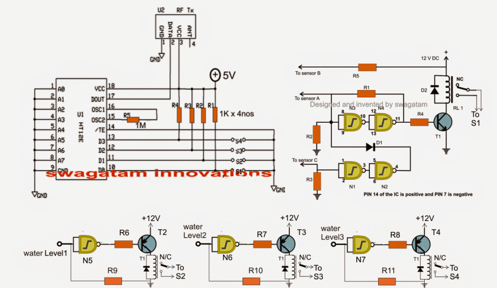
Here we incorporate two separate stages, one is our automatic water level controller circuit and the other is the RF remote control circuit.
Using Tx, Rx 433MHz RF Modules
The remote control has a Tx (transmitter) and and Rx (receiver). The transmitter is triggered through four discrete switches which encode and transmit the signals discretely into the atmosphere.
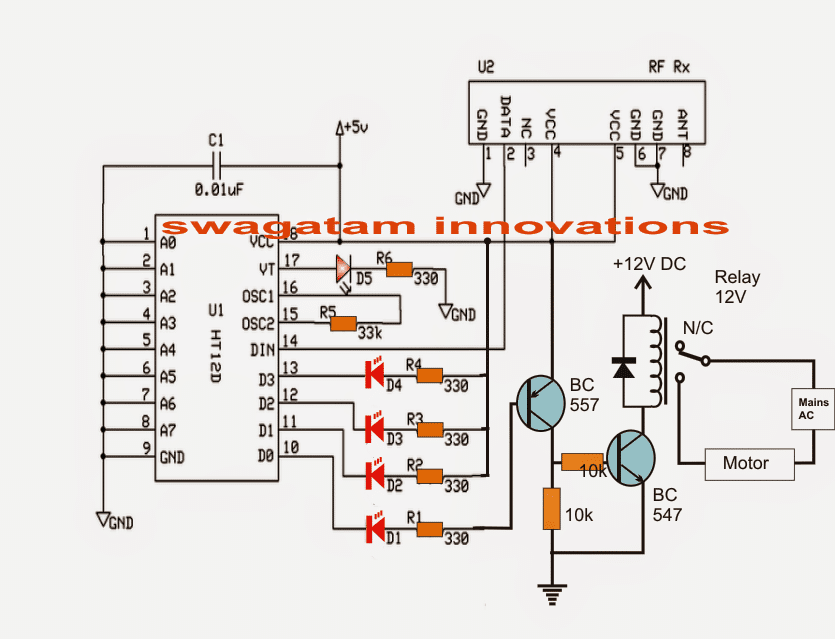
The receiver captures these signals, decodes it and sends it to one of the four outputs relevant to the decoded info.
This output responds by becoming high as long as the corresponding Tx switch is kept depressed.
The idea of the proposed water level controller through a remote control module is to press the Tx switches via relay contacts actuated by the water level controller circuit in response to the various water level conditions, as configured by the user.
The same has been implemented in the discussed design.
Referring to the figure, the gates gates N1 to N4 form the automatic water level controller circuit wherein the motor is switched ON when the level reaches a minimum lower threshold, and is switched OFF as soon as the level reaches the brim of the tank.
Originally Relay R1 was used for activating the motor by wiring its contacts to the motor and mains.
However for the present application, RL1 is rigged to one of the switches of the Tx module (S1)
Meaning now the Tx pin10 is engaged with the transmission of the signals as soon as RL1 is energized which happens on detection of an empty water tank.
Once this happens, the Rx responds by receiving the signals and triggering its own relay connected with the corresponding pinout.
This relay then activates the distant underground or overhead motor for the required water pumping.
The circuit diagram also shows three gates N5, N6, N7 which are configured as NOT gates for sensing the different water levels across the tank while the water is being pumped.
In the course these gates activate their own relays, which in turn close S2, S3, S4 for the necessary transmissions from the Tx to Rx.
The above transmissions are appropriately collected by the Rx, decoded and fed across its relevant outputs for illuminating the connected LEDs.
These LEDs provide the user with the info regarding the gradually filling water tank.
Thus the remote controlled triggering feature of the water level controller facilitates the owner a wireless and hassle free option of monitoring and controlling a distant situated tank.
The following figure shows the wiring details of the Rx or the receiver stage responsible for the toggling of the pump motor and various water level indications, in response to the Tx triggering signals.
Receiver Schematic
The RF modules can be sutudied in detail below:
https://www.homemade-circuits.com/2013/07/simple-100-meter-rf-module-remote.html
Parts List for the water level controller stage (N1----N4):
- R1 = 100K,
- R2, R3 = 2M2,
- R4, R5, R6, R7, R8, R9, R10, R11= 10K,
- T1 = BC547,
- T2, T3, T4 = BC557
- D1, D2 = 1N4148,
- All RELAYs = 12V, 400 OHMS, SPDT, contact amps as per load specs.
- N1, N2, N3, N4, N5, N6, N7 = IC 4093 (2nos.)
The last unused gate (N8) input must be terminated to ground or (+), output may be kept open.
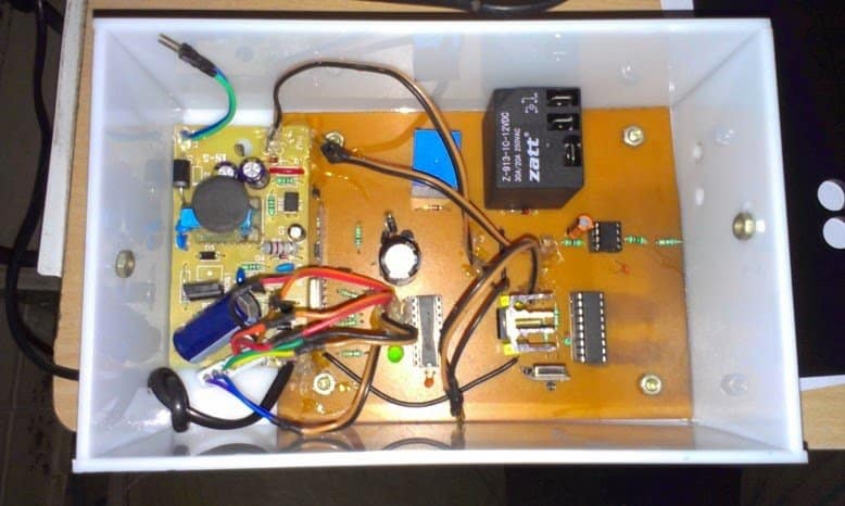
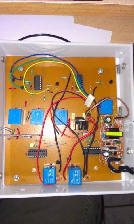
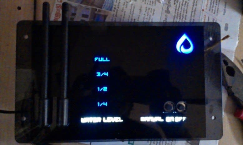
The above wireless water level controller circuit was built and successfully tested by Mr. Sriram kp. The following images exhibit the results of his outstanding efforts:


Questions & Answers
Hello Sir. What about the length and the nature of the antenna;. is it coiled reassemble an inductor? and how long should it be Sir?
The antenna can be made by connecting a long flexible wire , around 2 feet long, that’s all, it can be straight or coiled does not matter.
hello?I am not able to clearly understand where the connections of sensors A, B, and C should go in the transmitter circuit. Also, should the IC 4093 levels 1, 2, and 3 be shorted to ground inside the tank? It would be very helpful if you could provide the complete circuit diagram using IC 4093.
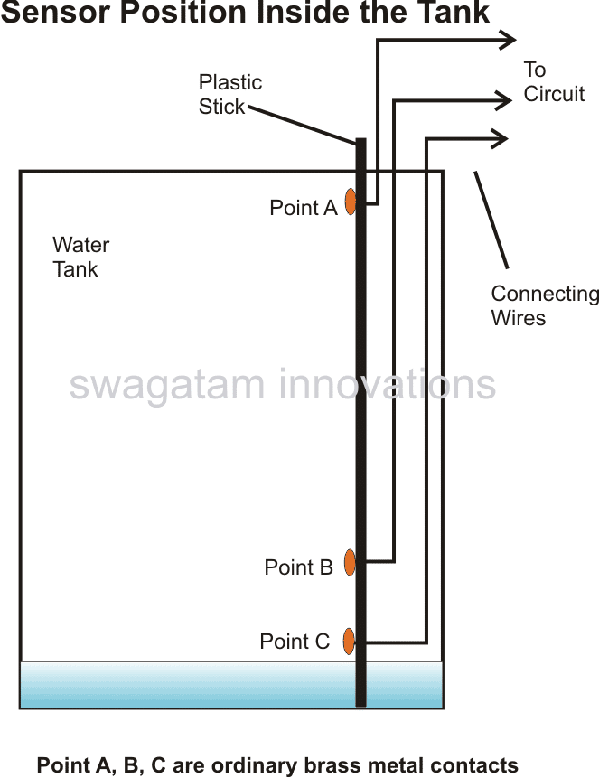
Hi, please see the following connection diagram for the tank probes:
The N5, N6, N7 inputs can be sequentially positioned above the probe B in the tank for monitoring the different levels of water in the tank…
Are the sensor connection points A, B, and C of S1 supposed to be shorted with Level-1, Level-2, and Level-3 points respectively and then connected inside the tank?
Brother, I’m saying that if you could make a complete circuit diagram using the CD4093 IC, it would be much easier for me to understand. So I kindly request you to do that.
Because I am a first-year electronics student, and I have already invested some money in this project.
Hi Priyam,
This circuit was posted many years ago, still, as far as i remember probes A, B, C does not need to be connected with Level-1, Level-2, and Level-3 points.
I would recommend you to go step-wise and first build the basic water level controller circuit using IC 4093 as described in the following article. Once you successfully build and test it then we can proceed to the next remote control version of the design.
https://www.homemade-circuits.com/how-to-make-simple-water-level/
“I have sent you an email. Please check it and give a reply if possible.”
Here’s the detailed tank probe position diagram:
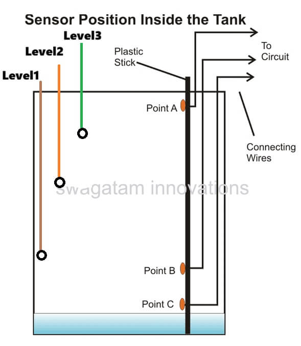
I have checked your diagram, according to me the N5, N6, N7 inputs does not need to be connected with the probes A, B, C. These inputs need to be installed separately, above the point B in the water tank.
Hello Sir.
a. The N5, N6, and N7; are they from the same CD4093 or are we using 2 CD4093 ICs? because the N1, N2, N3, and N4 seem to have depleted the 4 NAND gates contained in the CD4093.
b. N5, N6, N7 are NOT gates. Is it a different IC Sir?
Jedidiah, yes you will need more than one 4093 IC so that the shown number of NAND gates can be accommodated. All the gates are supposed to be from IC 4093.
How about using a NOT gate itself such as 74LS04?
You can use it, but do not exceed 5V for the supply DC.
Thank you
Thank you
hi sir can you please share me the detail of the encloser
The enclosure can be any suitable plastic enclosure, not a metal one…
if possible do have the dimensions of the encloser and stuff , and aslo sir which motor pump is good to use in this circuit can you please tell me
Rishi, you can use small plastic tiffin boxes as the enclosure, for both the units…any moderate power motor pump can be used if the relay is a 30 amp relay…
hi sir thanks for responding , I’m looking to add two tanks with two different transmitter unit and one receiver unit setting the unique code by dip switch on both end. but the thing is the commonets you use in this circuit are not avilable to purchace in North America do we have any substitute for component or for circuit ? it will be really helpfull
Hi Rishi,
The components used in the above circuit are standard components and they cannot be changed. I think you should try an online components spare part store and check the availability, I am sure you will be able to get all these parts online easily…
Hi swagatam
Thanks for clearing that up for me!!!! Your quick response is wonderful. Great website!!!!
It’s my pleasure Norman.
Hi Swagatam,
The above receiver circuit shows that D0-D3 of HT12D to produce a low output when the HT12E D0-D3 receives a ground pulse. I saw another posts that indicated a high at HT12D D0-D3. I’m confused!
Hi Norman,
D0-D3 of HT12D produces a low output when the when the HT12E D0-D3 receives a ground pulse, this has been tested and verified practically by the user discussed in the article. However, I myself have not verified it yet.
Need contact detail of PCB or Kit seller at Kolkata.
Sorry, I have no idea about it…
What is the battery life of this transmitter and receiver circuit ? In the comments I notice that there are comments which says that the circuit drains the battery very soon. I am planning to use it for my home purpose. I just need the water level indicator with alarm. i dont need the motor controller, etc. Is a readymade circuit available ?
Hi,
I didn’t understand what is N1, N2…. N7??
Hi, those are nand gates found inside the IC 4093
If you need it only for indication purpose then you can remove all the transistor and NAND gate IC based stages, and use only the basic Tx, Rx modules with LEDs. In the transmitter module the S1, S2, S3, S4 points could be used as sensors for immersing inside the tank at different heights, for sensing the water levels at those points.
The current consumption will be quite low, but till above 50 mA, and you will have to depend on a Li-Ion battery for long back up times.
Hello Sir, im trying to implement the above circuit. however the circuit is supposed to be battery operated. The transmitters have a current consumption of about 9 – 40mA (for ASK) which is not feasible as it’ll drain the battery quickly. Can you suggest any RF transmitters (433 MHz) having low power consumption. I have searched and found out that OOK modulation consumes low power. Can you suggest me some OOK transmitters and their internal circuit diagram ? Transmitters are desired to have a current consumption of about 4.5 – 5 mA for 5 V input and a range of about 100 – 300m
Hello Mihir,
you can try searching for “BC48R2020 315M/433MHz OOK Transmitter” you will be able to find the original HOLTEK datasheet
Hi Swagatam,
This remote-controlled-wireless-water-level looks good but I want only indicator not any relay to run motor. Can you please provide me simple circuit which will just indicate me about level through LED on unit which will be at lower level and people can act accordingly.
Looking forward for your response.
Hi Prem, you can try the following diagram:
The gate is from IC 4093.
Repeat the above circuit for pin11, 12, 13 of HT12E transmitter circuit.
In the receiver eliminate the transistor relay stage, and use only the LEDs for getting the required indications.
Please
Tell me resistance watt
all are 1/4 watt
Hi swagatham,
Thank u very much to your valuable reply that published in ur web page!.
Now I have an another doubt about the tx contro circuit.As you say I used a +5v relay in the circuit then ll compelsed to reduce the value of R5 as 220 ohm. Now it is working but some time do and not is the condition. That is why I cannot depend this tx vontrol unit. Actually what cn I do to get the accuracy for the circuit that need to be work properly means when ABC touches the water relay want to close and when AB leaves from waterand C lonely in water want to open the relay. Please be command.
And you can watch your corcuit how I made in reality: by opening the link
imgur. com/u5Edvtv and w.w.t.l control
Thanking you.
Thanks Abdlu, It's R4 and not R5 which needs to be changed to 220 ohms, I hope you did this right?
To increase accuracy, use a higher voltage supply inside water and check the response….if you are using 5V inside water then that might not work properly.
sorry your link is not working
hi swagatham,
I have a doubt about the above given article.can I control the tx and controling circuit completely with a +5 v power supply insted of +5,+12?.I want to control the tx circuit completely with a +5v supply by omiting +12v.is it possible? if so what changes need in the values of resistors?.please be helped
Hi Abdlu, it is possible if you don't intend to use a relay or if you replace the 12V relay with a 5V relay….no other changes would be required
Hai I have a problem and doubts in the circuit I have tried and failed so please give your number so I can contact u
Hi, you will need to build the various stages separately and confirm them separately before making the final unit…
you can specify your faults here I'll try to help
Hi I have tried this circuit but its not working I need help
pls give u moter dry run protection circuts
hi swagatam
After long time i build this circuit with all tests, but now i have one problem with range. When i operate rf module at a distance of 15ft each are at different room it works, but when i go to building terrace there is no activity at receiver. I have question regarding anteena,
1: What is length of anteena at both location?
2: What are the type of anteena?
3: i have 3 different pair of RF module, in which transmitter operate alternate but receiver section continuously on to receive signal. I used one common anteena for transmitter section and one common anteena for receiver section. is this ok?
4: is there need to use seperate anteena for separate receiver and transmitter?
please provide me guidance at this end point.
can u show me the complete circuit diagram
hai could you plese tell me that total howmany wires to be immersed in tank (3 sensors & 3 water levels)?…
for controlling the pump there are three wires to be inserted as shown in the first diagram (wires A, B, C), the remaining wires shown can be used only for indication purpose to learn the exact position of the water through the respective illuminated LEDs.
Can u plz post the complete ckt diagram once