In this article I have explained a generator/UPS/Battery relay changeover circuit for implementing a customized optimization for a generator, UPS, battery power network, in order to enhance the operational efficiency of the system. The idea was requested by Mr. Sidingilizwe.
Circuit Objectives and Requirements
- First of all thank you for adding me to your circles. Do you offer any lessons on electronics and programming for a fee?
- I am also looking for a circuit where a 10kva diesel generator supplies power to a UPS which in turn charges a battery bank.
- After about 8 hours the ups must stop the generator so that the battery bank supplies the power. When the power from the battery bank is drained, the generator will restart again.
- Every week I have to refuel a 10kva single phase diesel generator which is located in a remote area without electricity. The generator has a DeepSea 7220 controller.
- The generator mainly gives power to an OUTBACK UPS/battery charger combo which then charges a battery bank. The UPS uses 24v from the battery bank to power a load.
- I want to minimize the time I spend refueling. So I want a circuit which runs the generator for say 8 hours to charge the battery bank. After that, the generator should stop running so that the UPS can use the power from the battery bank to supply a load.
- The UPS should stop giving power to the load when the voltage of the battery bank drops to say 21v.
- And when it stops, the generator should start running to give power to recharge the battery bank again.
- The present scenario is that I always leave the generator running until it runs out of fuel.
- I want a circuit which will give time to charge the battery bank and then the generator must stop. Such a circuit will reduce the time I spend traveling to refuel the generator and the generator will last longer.
Circuit Diagram
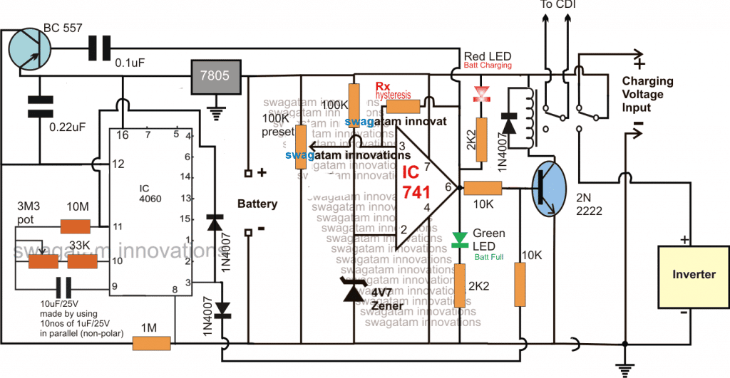
Note: The IC741 should be rated at above 24V...or replace it with LM321 IC
Designing Generator/UPS Changeover
As per the request, the objective of the design is to switch off the generator after 8 hours, and switch it ON when the battery reaches its lower discharge threshold.
To implement this generator/UPS/Battery relay changeover, I have introduced two options in the design, one is using the IC 4060 timer circuit and the second using the IC 741 opamp comparator circuit.
The timer and the opamp both are configured to switch OFF the generator depending on which one toggles first. If the 8 hour period lapses first, then its the timer which switches OFF the generator and if the battery gets fully charged before this period, the opamp takes the initiative and switches OFF the generator, and switches ON the inverter.
The opamp comparator is configured in the usual way using the IC 741, its pin#3 is rigged as the battery voltage sensing input while its pin#2 is used as the reference limit, as fixed by the zener diode voltage.
As long as the battery voltage level is below the desired full charge level, the pin#3 potential is lower than the pin#2 reference, resulting in an output pin#6 with a logic low, this in turn keeps the transistor and the relay switched OFF (N/C contacts at the upper side).
In the above situation the first set of contacts of the relay which is supposed to be associated with the generator CDI, keeps the CDI switched ON allowing the generator to be operational, while the second set of contacts receives the charging voltage from the generator to charge the connected battery.
The battery at this position keeps on charging until it has reached the predetermined full charge level, which causes a slightly more voltage to appear at pin#3 compared to the reference level at pin#2 of the opamp IC.
As soon as the above situation is detected, the opamp quickly changes its output stance and switches it to a logic high, turning ON the BC547 along with the relay.
The relay's sets of contacts now flick towards the lower N/O side.
The hysteresis resistor Rx comes into action and makes sure that the opamp stays latched ON in this position until the battery has discharged to some lower unsafe level.
The above action causes the first set of relay contacts to switch OFF the CDI so that the generator is switched OFF, and the second set of the relay contacts enables the battery to get connected with the inverter, allowing the inverter mode operation for powering the load.
On the other side, if suppose the timer circuit which is made around the versatile 4060 IC becomes the first to switch ON (8 hours lapsed) before the opamp, its pin#3 goes high, and it sends a switch ON signal for the transistor relay driver stage.
This implies that in this position the battery may not be fully charged but may be close to the full charge level. However since the inverter needs to be switched ON anyhow even with whatever charge may be available from the battery, the relay is toggled ON by the 4060 output for executing the inverter mode operations.
The battery now begins discharging through the inverter, and after a course of time when it reaches its lower discharge threshold, the opamp hysteresis resistor succumbs to this lower level and releases the opamp latch.
This instantly reverts the opamp output situation and produces a low logic at its pin#6.
This low logic from the opamp does a few things in order to restore the situation the earlier condition:
First it switches OFF the relay switching ON the generator back and initiates the charging of the battery, additionally the low logic also sends a short triggering pulse to a PNP BC557 transistor which resets the 4060 timing and ensures that it makes a fresh start and begins counting from zero.....until 8 hours have elapsed yet again to keep the cycle moving.
The above explained generator/UPS/Battery relay changeover circuit for optimizing the generator, UPS, battery network power efficiency ensures a cyclic turn by turn operation of the stages and makes use of the resources in the most effective and optimal technique producing lower maintenance for the units, and increasing cost saving for the end user.
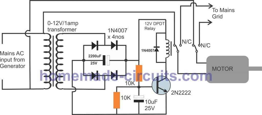
Generator Motor Auto Transfer Circuit
The following diagram shows an automatic transfer system designed to changeover mains supply from grid to the generator motor, as soon as generator starts generating power. More info can be found in the comment discussion below with Mr. SAA Bokhari


Questions & Answers
Dear Mr. Sawagatam, I have a Schneider inverter/charger CSW4024, it has a 24V battery bank charged via solar panels. I bought a Schneider AGS to use with it to turn the generator on when batteries hit 21v and turn off when it gets back to 26.2 V. I do not know how to connect the ags and the generator. I guess I would have to send the wiring diagram of the generator to you as well as the AGS harness wiring. But I am lost LOL
Dear Tony,
I really wish I could help you, however it can very difficult for me to solve this for you because I have never used a Schneider inverter/charger CSW4024, therefore I have no idea how to implement the wiring of this specific inverter…I can only help with general circuits and wiring issues.
I really just need to set up a relay that will trigger the generator to start and stop depending on the battery charge. but thanks for your quick response.
Now that ic 4060 is hard to get here in ma country,,does timer ne555 works here?
Another thing,can get of changeover circuit of Ac main and inverter to ma workshop appliances,where that when main AC blackout it changes to inverter to work without interference,then when AC comes back it switches inverter off
Sorry, IC 555 will not work in this circuit, since 555 cannot be used for getting long duration timings.
For the changeover circuit, you can try the following concept:
https://www.homemade-circuits.com/automatic-inverter-supply-and-mains/
Dear Mr. Swag,
It is not a free energy but a fuel less mechanical energy generation. My system is running perfectly. Motor is consuming maximum five Amps and generating about 22 Amps. I want to shift motor supply on generated supply as already explained in my last request. I shall be grateful if you please design a changeover as requested.
Thanking you once again.
Dear Mr. SAA Bokhari,
I have updated the diagram at the bottom of the above article, you can check it out.
Dear Mr. Sawagatam,
I have made a Fuel-less Generator by using Flywheels. I start revolving Flywheel with 3 HP (three phase Motor) through VFD inverter using 220 single phase home supply. Avery thing is running fine but I have been facing problem in transferring Motor supply from home to Generator. When I have been trying to change through changeover switch the VFD Invereter showed power off. I need RELAY (ATS) system that as soon as the Generator starts producing power, the driving Motor must immediately shift on Generating power and supply from home connection should be cutoff. I shall be grateful if you kingly design a suitable circuit.
Thanking you and best Regards
SAA Bokhhari
Dear SAA Bokhari, I’ll try design it for you soon…!!
Dear Mr. Swag,
Thanks for your promise to design for me a circuit of changeover for Motor supply from home to Generator. I shall be waiting for the design.
Dear SAA Bokhari,
Before designing I would like to confirm it.
From your explanation I have understood the arrangement to be as follows:
You have a generator that’s operated with a motor.
This motor is run either by the home 220V supply or from VFD inverter 220V supply.
You want a circuit that should automatically cut off the home 220V to the motor immediately, whenever the inverter is initiated to power the motor.
Please let me know if the requirement is correctly understood by me or not?
Dear Mr. Swag,
Yes, you have correctly understood the arrangement with a little modification. I repeat the arrangements as under in a chronological order:
1. I have a Generator that operates with a 3 phase ac motor.
2. This motor is run with a VFD inverter and the inverter is connected with 220V single phase home supply.
3. The motor operates Flywheels and the Flywheels run the connected Generator with them.
I want a circuit, that as soon as the Generator starts producing electricity (220V ac), that should automatically cut off the Home supply and the inverter should run on the Generated supply and inverter is initiating to power the motor.
I hope that the above explanation certainly will help you to understanding what I want exactly.
The circuit should be sufficient from 3-kw to 10-kw generation.
Mr. Swag, I shall be thankful for your help.
Dear SAA Bokhari,
From your explanation it appears you are trying to develop a free energy perpetual device, right? however I am afraid that can never work, and has never ever worked for anybody so far.
If you are not able to implement it with manual switching, automatic would also not work, that’s for sure!
So designing this circuit will not benefit anybody, I’m really sorry about it!
My question is can this circuit be used for 12v instead of 24v, if so what changes need to be made?
I am enjoying looking through your site to see what circuits you have. Thank you much for the help.
you can use the circuit with a 24V supply also, just make sure to supply pin#4 of the opamp with a 12V or a 5V, or replace the opamp with IC LM321 and use replace the relay with a 24V relay
Hi
Need a circuit to detect deep cycle 24v battery 50%/40%/30% discharge and changeover to an alternative supply ie generator start and also stop generator when batteries fully charged and reconnected
Hi, I’ll try to update it soon in this website…
heloo i want a mpatary garger for 12v 7ah for mpatary car auto cut off full in the car.thank you.
what is mpatary garger ??
select Rx such that it produces a voltage less than pin#2 zener voltage at pin#3 when the battery voltage drops to the mentioned level.
hi
i want to use solar system to run 700watt equipment's for 16 hours in my area we have sunny 7 hours. how many watts of solar panels and batteries i have to buy ? And how will i connect the batteries in series or parallel
For a 700 watt load to run for may be 10 hours you will require over 600AH battery
Calculations
divide 700 by battery voltage then multiply it by 10 hours, that will give you the approximate AH value for the battery, multiply it further 10% of its AH rating to compensate the inefficiencies.
you didn't get me i buy solar panels of 120watt *17 to get the 2000watt u said on the battery i will buy 150Ah but i don't know how many will be enough for my project that why i nee your help
it won't be sufficient for the mentioned purpose
i will use solar panels of 120 0r 150 watt 150Ah
Hi, for 700 watt equipment to run 16 hours would require a 700 x 16 = 11200 watt-hour electricity source.
with 7 hour sun light, we can divide the above figure with 7…11200/7 = 1600 watts
therefore a solar panel rated at 1600 to 2000 watts would be required,
specify your battery or solar panel specs I'll try to help with the further procedures.
Thanks again for the super fast response. That was awesome. May I know if there is a specific type of capacitor that I may use?
Sidingilizwe Ndiweni
thanks so much! all the parts are standard, including the capacitors, but the IC 4060 capacitors should be non-polar type strictly.
the IC 741 must be rated to handle over 24V or you can replace it with a LM321 IC which is similar to 741 and is rated at 32V