In this post I will show how to construct a digital clock using 7 segment LED display with Arduino controlled design.
How the Circuits Works
The proposed 7 segment clock circuit is inexpensive and even beginner in Arduino can accomplish it with ease. This clock consists of four 7 segment displays, two for hours and two for minutes.
The display is paired with IC 4026 which is designed for driving 7 segment displays. Each IC 4026 is controlled by Arduino.
This clock has beep alert function, which beeps every beginning of the hour, giving a rough idea about time without looking at the clock. This clock does not have alarm function.
The Arduino code doesn’t need any special library for compile the program. The clock has very minimalist design, just four displays and two LEDs for AM/PM indicator and no fancy functions other than beeping every hour.
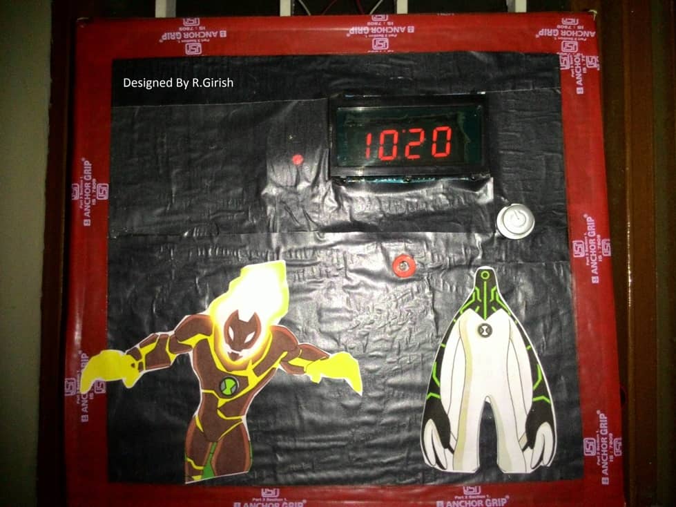
Author’s prototype:
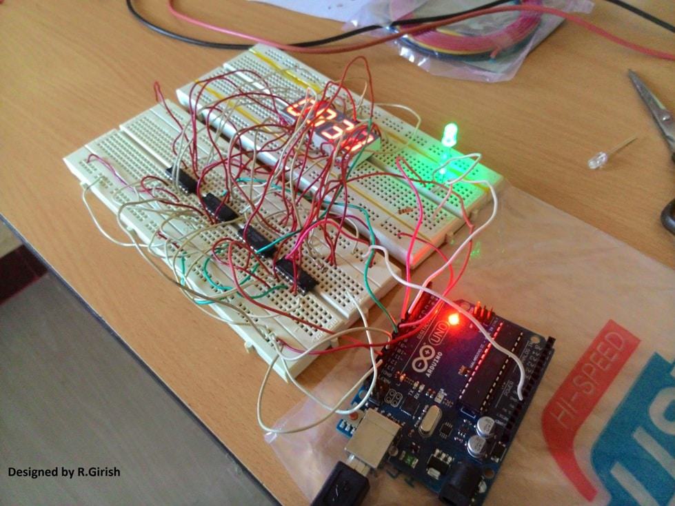
Here is a completed prototype using cardboard and scrap materials:
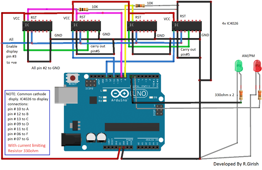
The Design:
The circuit consists of four IC 4026 for controlling four 7 segment displays and the brain of the clock arduino. Two pull down resistors are connected to reset pin of IC 4026 to avoid accidental reset due to static charge. AM/PM indicator connected to arduino in combination with 330 ohm current limiting resistor.
Note: 220 ohm to 330 ohm resistor should be connected each segments of display.
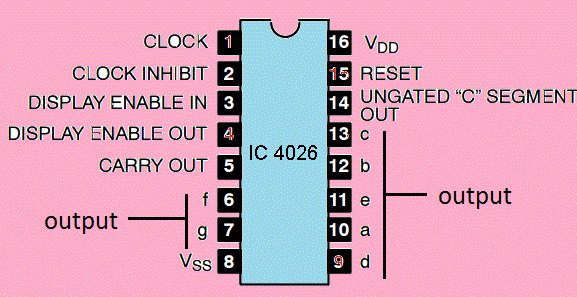
Pin configuration of IC 4026:
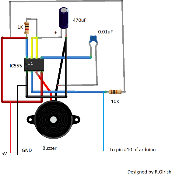
The beeper circuit:
The beeper circuit is just a monostable multivibrator designed using IC555. When a negative pulse is fed to pin #2 of IC555, it beeps roughly for one second. This audio alert helps the user to keep a rough idea about the time. The pin #2 of IC555 should be connected to pin # 10 of arduino.
Program Code:
//---------Program developed by R.Girish---------------//

int mint=13;

int hrs=11;

int beep=10;

int rst=8; // reset to mint ic.

int rsth=9; //reset to hrs ic.

int am=7;

int pm=6;

int y=0;

int t=0;

int x=0;

void setup()

{

pinMode(beep,OUTPUT);

pinMode(hrs,OUTPUT);

pinMode(am,OUTPUT);

pinMode(pm,OUTPUT);

pinMode(mint,OUTPUT);

pinMode(rst,OUTPUT);

pinMode(rsth,OUTPUT);

}

void loop()

{

digitalWrite(beep,1);

digitalWrite(13,0);

delay(10000);

delay(10000);

delay(10000);

delay(10000);

delay(10000);

delay(10000);

digitalWrite(13,1);

t=t+1;

if(t==60)

{

digitalWrite(rst,1);

digitalWrite(rst,0);

digitalWrite(hrs,1);

digitalWrite(hrs,0);

digitalWrite(beep,0);

digitalWrite(beep,1);

x=x+1;

y=y+1;

t=0;

delay(2000);  // error fixing (varies with temperature)

}

if(x==13)  // display 1'O clock after 12'O clock.

{

digitalWrite(rsth,1);

digitalWrite(rsth,0);

digitalWrite(hrs,1);

digitalWrite(hrs,0);

x=1;

}

if(y<12)

{

digitalWrite(am,1);

digitalWrite(pm,0);

}

if(y>=12)

{

digitalWrite(pm,1);

digitalWrite(am,0);

}

if(y==24) y=0;

}

//---------Program developed by R.Girish---------------//
How to set time:
Being very minimalist design the “reset button” can be used to set time. But the user has to set the time with the help of reference clock. The user has to reset the arduino at exactly 12’O clock. One this is done the clock updates the time on its own.
Note: Since the above explained 7 segment digital clock using Arduino does not have “real time clock chip”, for maintaining accurate time, there is possibility that the time may lead/lag due to change in the ambient temperature.
To rectify this here are the steps:
• If your clock leads the time of reference clock by few seconds it need to be slow down, note down the difference and enter the value in the program in milliseconds.
delay(2000); // error fixing (varies with temperature) This will slow down few seconds every hour.
• Replace 2000 with your value.
• If you clock lags set the “delay(0); //error fixing(varies with time)” and make the following changes in the program:
delay(10000);

delay(10000);

delay(10000);

delay(10000);

delay(10000);

delay(10000);

to

delay(10000);

delay(10000);

delay(10000);

delay(10000);

delay(10000);

delay(9700);
Replace “delay(9700);” with your value to speed up the time every minute.
These steps do not guarantee that time will be always accurate, but it helps to maintain the time with minimal inaccuracy. The proposed design is 12 hour clock.
What modification hard ware and software will be required for common anode type display for little bigger size like 1.5 inches display
According to me, the same design can be used for the mentioned display also!
ahh can you make an alarm clock?
alarm clock, like the same with that 7 segment LED.
If possible I’ll update the design soon
okay, hope you can make it this week .
thanks..
Sir, instead of 4026 IC, we got 4511. Is there a way we could use this IC instead of the 4026?
Thanks ^_^
Kwintoy, it is possible but the circuit configuration will be different
can we use the same code?
No that won’t work…
What kind of 7 seg display is used, CA or CC type, can I use 1 inch size 7 seg display
common cathode, it's been provided in the diagram
How can I write output of arduino to any txt file in my pc only…
That's great Mr.Devendar, I am glad you liked it!
Wish you all the best!!