• Skip to main content
  • Skip to primary sidebar

Homemade Circuit Projects

Need circuit help? Post them in the comments! I've answered over 50,000!

Blog | Categories | About | Contact | Calculators-online
You are here: Home / Battery Charger Circuits / What is T856-C Power Bank Module? How to Connect

What is T856-C Power Bank Module? How to Connect

Last Updated on April 15, 2025 by Swagatam 3 Comments

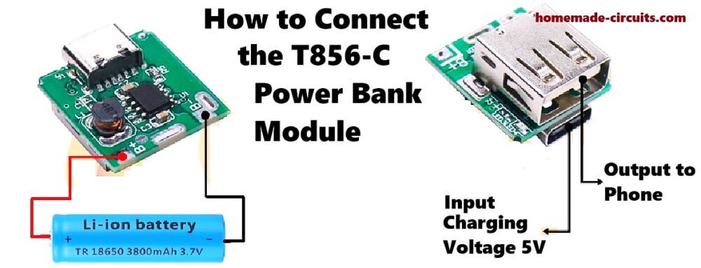
So here we are talking about one small board called T856-C. We use this little module when we want to make one DIY power bank at home, like those we use to charge phones and other USB things. It can charge one 3.7V Li-ion battery like 18650 and also give us 5V output to run or charge other gadgets from USB.
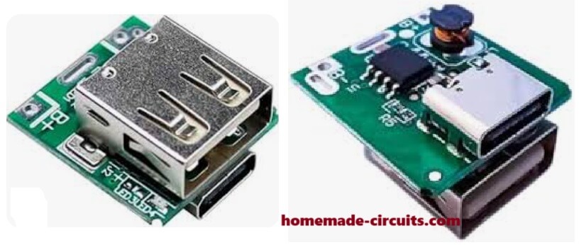
Table of Contents
  • Ports and Pins – What We See On This Module
  • Battery Details – What Battery We Use
  • LED Indicators – What Lights Tell Us
  • How We Connect Things – Step by Step
  • Protections Inside This Module
  • Some Crude Tips and Advice

Ports and Pins – What We See On This Module

USB Type-C Port:

This port is used for charging the battery. We give 5V DC input here, from phone charger or power adapter.

Current needed is around 1A, not more than that.

USB-A Port (big normal USB):

This one is the output. From here we get 5V output to charge mobile or run USB fan or something.

Max current here can go around 1A or a little more, depending on battery power.

Battery Points:

On the board we see + and – markings where we solder the 3.7V Li-ion battery.

If we want long backup then we can join 2 or 3 batteries in parallel (not in series, only parallel) but all batteries must be same voltage and type.

Battery Details – What Battery We Use

Best battery is 3.7V 18650 Li-ion cell, single or more in parallel.

When we give charge, board sends 4.12V to 4.20V to battery side.

If we join more than one battery then we always connect them parallel, not series.

LED Indicators – What Lights Tell Us

LED Light Doing ThisWhat That Means
BlinkingCharging is going on now
Always ONBattery is full or giving power out

How We Connect Things – Step by Step

First we solder battery:

Take the + and – of battery, solder to board's battery pads marked + and –.

Be very careful, if we reverse battery wires then it can damage the board.

Then we charge:

Take normal 5V USB charger, then connect it to Type-C port.

Now charging will start.

Then we use output:

When battery is charged, then we plug USB device in the big USB port, and it starts working.

Output comes as 5V, can run or charge any USB thing.

Protections Inside This Module

This board is smart and has few protection features like:

It stops overcharging the battery.

It protects from over-discharge.

If something short happens, it cuts off the output.

It boosts battery 3.7V to 5V automatically.

Some Crude Tips and Advice

We must use good and healthy battery, not damaged or over-discharged one.

If we want long backup then we can connect 2 or 3 batteries in parallel, but all must be same brand and type.

Never try to connect batteries in series, it will mess up the circuit.

This small board is good for DIY power bank, also useful for solar charging projects or making small USB power supply.

You'll also like:

  • 1.  High Voltage Battery Charger Circuit
  • 2.  How to Illuminate 1 Watt LEDs with Cell Phone Charger
  • 3.  5 Best 6V 4Ah Automatic Battery Charger Circuits Using Relay and MOSFET
  • 4.  How to Switch Two Batteries Manually using Opto Coupler
  • 5.  How to Set IC 741 for Auto Cut-oFF
  • 6.  6 Useful DC Cell phone Charger Circuits Explained

Filed Under: Battery Charger Circuits Tagged With: Bank, Connect, Module, Power, T856

About Swagatam

I am an electronics engineer and doing practical hands-on work from more than 15 years now. Building real circuits, testing them and also making PCB layouts by myself. I really love doing all these things like inventing something new, designing electronics and also helping other people like hobby guys who want to make their own cool circuits at home.

And that is the main reason why I started this website homemade-circuits.com, to share different types of circuit ideas..

If you are having any kind of doubt or question related to circuits then just write down your question in the comment box below, I am like always checking, so I guarantee I will reply you for sure!

Previous Post: « Adjustable 1.2V to100V DC Buck Converter Circuit using LM5164
Next Post: What is ISD1820 Module? How to Connect and Use »

Reader Interactions

Comments

  1. Nitesh Agrawal says

    April 21, 2025 at 1:16 pm

    Thanks

    Reply
  2. Nitesh Agrawal says

    April 21, 2025 at 10:37 am

    Dear Sir
    i have power bank & one time circuit connect with MOSFET While my time is on power bank gives power & MOSFET ON & while my timer is OFF ,power bank goes into sleepmode.
    how can i prevent power bank goes into Standby MODE. May i connect some external load into my circuit?

    Reply
    • Swagatam says

      April 21, 2025 at 11:59 am

      Hi Nitesh,
      Yes, you can try adding any dummy resistor load between 1k and 10k at the power bank output and check if the issue is solved or not…

      Reply

Need Help? Please Leave a Comment! We value your input—Kindly keep it relevant to the above topic! Cancel reply

Your email address will not be published. Required fields are marked *

Primary Sidebar

circuit simulator image

Subscribe to get New Circuits in your Email

Categories

  • Arduino Projects (89)
  • Audio and Amplifier Projects (132)
  • Automation Projects (17)
  • Automobile Electronics (101)
  • Battery Charger Circuits (83)
  • Datasheets and Components (106)
  • Electronics Theory (143)
  • Free Energy (37)
  • Games and Sports Projects (11)
  • Grid and 3-Phase (19)
  • Health related Projects (25)
  • Home Electrical Circuits (12)
  • Indicator Circuits (14)
  • Inverter Circuits (88)
  • Lamps and Lights (142)
  • Meters and Testers (69)
  • Mini Projects (46)
  • Motor Controller (64)
  • Oscillator Circuits (28)
  • Pets and Pests (15)
  • Power Supply Circuits (108)
  • Remote Control Circuits (50)
  • Security and Alarm (64)
  • Sensors and Detectors (102)
  • Solar Controller Circuits (59)
  • Temperature Controllers (42)
  • Timer and Delay Relay (49)
  • Transmitter Circuits (29)
  • Voltage Control and Protection (40)
  • Water Controller (36)

Other Links

  • Privacy Policy
  • Cookie Policy
  • Disclaimer
  • Copyright
  • Videos
  • Sitemap

People also Search

555 Circuits | 741 Circuits | LM324 Circuits | LM338 Circuits | 4017 Circuits | Ultrasonic Projects | SMPS Projects | Christmas Projects | MOSFETs | Radio Circuits | Laser Circuits | PIR Projects |

Social Profiles

  • Twitter
  • YouTube
  • Instagram
  • Pinterest
  • My Facebook-Page
  • Quora
  • Stack Exchange
  • Linkedin
  • Recent Comments

    • Swagatam on Crystal Radio Sets with Amplifier Circuit
    • Swagatam on 9 Simple Sine Wave Generator Circuits Explored
    • Gazza on 9 Simple Sine Wave Generator Circuits Explored
    • Gazza on 9 Simple Sine Wave Generator Circuits Explored
    • Lion on Crystal Radio Sets with Amplifier Circuit

    © 2025 · Swagatam Innovations