In this post I have explained a simple circuit design which ensures a perfectly stabilized 220 V or 120 V mains voltage across the connected load, without using relays or transformers, rather by the use of accurately dimensioned and self adjusting PWM pulses. The idea was requested by Mr. Mathew.
Warning: Circuits I have explained below are not isolated from mains AC, and therefore are very dangerous to touch in the powered and open condition. You should be extremely careful while building and testing these circuits, and make sure to take the necessary safety precautions. The author cannot be held responsible for any mishap due to any negligence by the user
Technical Specifications
About power optimizer (stabilizer) I need a simple circuit board which can be installed in our power guard ( capacitor bank) with SPD and ELCB for 1ph and 3ph.
At present we are producing it without any electronics circuit in it. So we are planning to add one circuit board for power optimizer to balance the voltage drop or over voltage.
Our product is in a good demand, So we are planning to introduce our power guard with a voltage stabilizer for our 1ph and 3ph unit. In this case we need a very simple less cost circuit board for our new models.
I hope you understand what I need exactly. As I told you in my earlier mail that if you can design the PCB or supply PCB with components will be an advantage because in our country components is very difficult to find. Our 1ph is 220v/50Hz with 12k and 3ph /415v/50Hz 40k
I look forward your reply soon.
Kindly add me in Skype for any discussion or in viber , whatsup Thanks Mathew
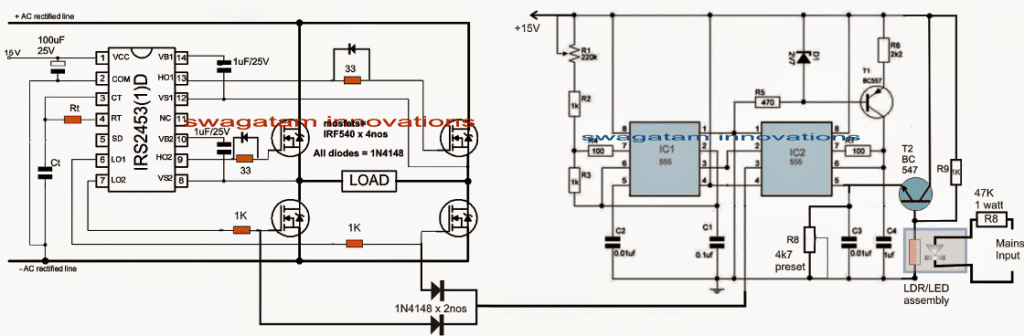
The Design
As requested, the mains voltage stabilizer needs to be compact and preferably a transformerless type. Therefore a PWM based circuit looked to be the most appropriate option for the proposed application.
Here the mains AC input is first rectified to DC, then converted to a square wave AC, which is finally adjusted to the correct RMS level for obtaining the required stabilized mains output. So basically the output will be a square wave but controlled at the correct RMS level.
The Rt/Ct of the IRS2453 IC should be appropriately selected in order to obtain a 50 Hz frequency across the H-bridge network.
The shown PWM mains stabilizer circuit basically consists of two isolated stages. The left hand side circuit is configured around a specialized full wave H-bridge inverter IC, and the associated power mosfets.
To learn more about this simple yet highly sophisticated H-bridge inverter, you may refer to this article named: "Simplest full bridge inverter circuit"
As may be seen the diagram, here the intended load is placed across the left/right arms of the full bridge mosfet.
The right hand side circuit which is made by using a couple of 555 IC stages forms the PWM generator stage, wherein the generated PWM is mains voltage dependent.
Here the IC1 is configured to generate square wave signals at a particular set consistent rate, and feeds the IC2 for transforming these square waves into corresponding triangle waves.
The triangle waves are then compared with the potential at pin#5 of IC2 in order to generate a proportionately matching PWM signal at its pin#3.
That implies, the potential at pin#5 can be adjusted and tweaked for getting any desired PWM rate.
This feature is exploited here by attaching an LDR/LED assembly along with an emitter follower across the pin#5 of IC2.
Inside the LED/LDR assembly, the LED is tied up with the mains input voltage such that its intensity proportionately varies in response to the varying voltage of the mains.
The above action in turn creates a proportionately increasing or decreasing resistance values over the attached LDR.
The LDR resistance influences the base potential of the emitter follower NPN, which accordingly tweaks the pin#5 potential, but in an inverse ratio, meaning as the mains potential tends to increase, the potential at pin#5 of IC 2 is proportionately pulled downwards and vice versa.
As this happens the PWM at pin#3 of the IC is narrowed as the mains potential increases and widened as the mains decreases.
This automatic adjustment of the PWMs is fed at the gates of the low side mosfets of the H-bridge which in turn makes sure that the voltage (RMS) to the load is appropriately adjusted with reference to the mains fluctuations.
Thus, the mains voltage becomes perfectly stabilized and is maintained at a reasonably correct level without using any relays, or transformers.
Note: The rectified DC bus voltage is obtained by appropriately rectifying and filtering the AC mains voltage, so here the voltage could be well around 330V DC


Questions & Answers
hai swagatam ,
i need to convert dc 700 volt to ac and reduce it to low voltage for battery charging ,because i have panels connected series for agri 5 hp solor pumpset which is run by solor vfd ,so i dont want to disturb the connection and i want to keep changeover switch inbetween dc bus voltage from panels and use it to home by ups when not in agri use
Hi shiva,
you can try the simple buck converter circuit shown in this article:
https://www.homemade-circuits.com/2014/06/solar-panel-buck-converter-circuit-with.html
just make sure tat the transistors, capacitors and the mosfet are all rated at above 700V
the circuit that you have referred is a simple low power inverter circuit, and it's a step-up inverter, it cannot be used for stepping down a voltage.
for stepping down a voltage you'll need a buck converter as suggested by me in the earlier comment or you can also use a buck flyback converter for the same.
Google "buck flyback converter circuit", you will find many good examples.
the circuit is very useful. it can be made more practical if it included the calculations for Rt & Ct. Thank u
thanks, Rt, Ct can measured with meter by experimenting practically…. or the IC datasheet online can be consulted for the same.
hello swagatam,
I really need your assistance. I have three questions and their answers will help me a lot.
1. why pin5 of irs2453 was not used?
2. since pin1 of irs2453 requires +15vdc, where will I connect the ground of that +15vdc?
3. can i use 220uf/16v instead of 100uf/25v at pin1 of irs2453?
hello afam, pin5 is the shut down pin of the IC, it can be left unused if not implemented.
the negative 15V or 12V can be applied to pin2 or to the mains rectified negative line
220uF/25V can be used but not 220/16
please, why my irs2453 always got damaged anytime i power this circuit? first, it was my bridge diode and mosfets. i made another rectified AC with current surge components (varistor and thermistor) and it was solved. Now is the IC that got damaged and i was guessing it was the pin5 that was not used. Plz help me.
there,s no way the IC can get damaged because it's protected from all sides, check your connections properly.
Dear R8 mains input should be 220vac or 12vac?
220VAC
Dear Sir, my query is related more to electricals rather than electronics. Still kindly advise on following- Can a circuit be made which prevents voltage fluctuations to be passed on to electrical appliances (220V). Commonly stabilizers are used, but even the automatic ones just increase or decrease the output voltage in response to input voltage, BUT the fluctuations are still there, thus damaging sensitive electrical appliances. In other words, can a circuit be designed which gives a constant output by utilizing large capacitor etc so that input fluctuations are not manifested in output voltage. ( The appliance concerned is a motorized treadmill with a 1.5 HP motor which is said to require a 3 KVA voltage stabilizer).
Dear Ankit, through capacitors it cannot be possible, PWM is the only way this can be implemented effectively as expressed in the above article.
Thanks Sir, for the reply…Just one more clarification please… Is any modification required in above circuit so that it can be used for 3 KVA load.
Thanks
i am looking forward to building it sir, what will be the output rating (voltage,power)
will it produce 220v stabilised AC?
2)how much load can it handle ?
3)and how much approximately will it cost (INR)?
thank you so much sir
Asim, the voltage will be equal to the existing mains supply, power will depend on the load and the mosfet specifications. for higher loads you will need to upgrade the mosfet rating accordingly.
it could cost anywhere from Rs.400/-
Hello want to know in H bridge section what is load is there any transformer or our load like any LED Light ?
the load is your appliance which you would want to operate with the circuit's stabilized voltage
hello Swagatam Majumdar thankx for your reply,
LDR/LED assembly can replace with any optocoupler or any special number can you tell which you use ?
OR
homemade assembly in black heat shrink sleeve
(led colour ? red,green or white)
thanks
Hello Hkhurram, any opto will not do, only LED/LDR opto will work….but a better option would be to create a potential divider at the base of the BC547 and connect one end of this potential divider with the mains rectified DC, and the other end to ground…then adjust this potential divider such that at normal 230V, the PWM are set to allow 230V for the load, and as the voltage increases, this potential divider voltage also increases causing the PWM to become narrower and in turn prevent the 230V from increasing for the load
Thanks swagatam
Hello Mr. Swagatam. Could this design be modified in such way that it can be used as a grid tie inverter without the use of a large transformer (transformerless)? Best regards.
Hello Mr. Gustavo, yes that's possible by integrating the pin#5 of the IC2 555 with the grid mains through a potential divider network
…sorry, but what happens when the grid fails, there has to be a DC input equivalent to the grid mains level for the inverter to function, that's why we need a transformer, or a DC source that's itself is at the 220V or 120V level…
Thanks for quick reply. Excuse my lack of understanding, but pin #5 is not connected yet with the grid mains via ldr/led assembly? Regarding grid failure, I'm thinking of implement some kind of detector circuit that rapidly switch to a PWM generator instead of the signal comming from pin # 3 of the IC2. By the way, I think you clearly noticed my poor english so I apologize for it. Regards.
Gustavo, Actually the pin#5 must be integrated with the grid mains so that the the 555 circuit is able to monitor the mains level and adjust the PWMs accordingly.
In a grid tie application the above circuit must have a capability of replacing the grid voltage with its own mains level voltage through a battery, or any other DC source such as solar DC, but the above circuit presently has no such feature included, and thus needs to be upgraded for a GTI implementation.
By the way your English is very good…well understandable.
Hello Swagatam. I made a schematic based on your design to convey a clearer idea, check it please in the following link:
https://1drv.ms/i/s!AtyAGimmWHaZhGZ6_21C0ao-AW4p
The idea is as follows: In case of mains failure, the AC voltage detector block will turn on the PWM signal generator performing the same work made by IC1 and IC2, thus, the igbt H bridge will still supplying AC power. If we have power from mains again, the AC voltage detector block will turn off the PWM generator and switch the source back to the signal that is being generated by IC1 and IC2.
By the other hand, as I can see, there is a led and a ldr connected to the base of the T2 bjt wich in turn is connected to pin #5 of IC2. I think this way IC2 is tied to the AC mains, or please correct me if I'm wrong.
Please give me your opinion.
Regards.
Hello Gustavo,
your idea makes sense because it has a renewable source attached so now it looks like a valid GTI circuit.
yes the LED/LDR is supposed to be integrated with mains for sensing the mains voltage levels and auto adjusting the PWMs accordingly.
by the way since the IC2 is tied to AC mains, when the AC mains fails, there will no potential at pin#5 which will prompt the IC2 to produce maximum PwMs and maximum renewable AC will now be supplied to the grid…therefore I think the external PWM stage may not be required…
yes it can done by employing any standard transformerless power supply with the design.
yes that would be hugely expensive compared to the above 555 based design…at least 10 times more
sir i want to make a tranformerless voltage stablizer circuit which can stablize the 90-300 ac volts to 220 volts and 50 Hz frequency. can u help me in doing this??
If you want to boost the input from 90V to 220V then transformer will be required, it may not be possible without a transformer.
thanks for your reply sir how much voltages can be boost to 220V without transformer??
Muhammad, without a coil or transformer even a single volt cannot be boosted. an inductor or a coil is a must for stepping up a voltage level
then what about the inductor how much voltages can be boosted from inductor??
actually i am electrical (power) engineering student i am seeking some innovative idea for my final year project, can u suggest me some innovative idea??
using coil you an boost at any desired level, by proper calculation,
one example of a compact inductor based stabilizer can be seen below
https://www.homemade-circuits.com/2016/05/h-bridge-mains-voltage-stabilizer.html
thank you so much sir can u give me some suggestion/idea for my final year projet related to power??
there are many small projects published in this website, you can easily select any appropriate one as per your preference…you can use the search box on top to search a potential concept.
thanks sir
Hello Mr Swagatam,
Hope you are doing good.
Actually I am thinking if there is a way to make a voltage stabilizer which produces constant output with or without transformer for home appliances.Is there a way to make it at home considering already have a stabilizer which is relay based. The stabilizer can be uses with 5k watts full load.
The problem is that this relay type voltage control is very irritating when fluctuation is high.
Could you please direct me how to do it, and if possible, the circuit diagram with component will be more convenient.
I am continuously reading your post and really telling you when I did by Btech, there was no such a wonderful website to help the students. Anyway thank you so much for doing the good job.
Shadab
Hi Swagatam,
Thanks for your nice posts.
Actually I want to know if there is a possibility to convert my automatic relay based stabilizer of 5kva used for domestic appliances to a constant voltage regulator. Because the relay based controls are some time irritating when fluctuation in power supply is high.
Please guide me to build a constant voltage regulator to carry a load upto 5kva. If possible, please tell me the circuit diagram with component details.
Thank you Shadab, I am glad you are enjoying my posts.
If the stabilizer circuit is without a transformer it will be only able to prevent the voltage from rising over the specified limit and regulate it at a constant level only as long as the voltage is above this minimum threshold…but if the voltage drops below this threshold then the stabilizer will not be able to boost it…because there's no transformer….
But if a trafo is present as it is in your case then it can be definitely converted into a silent stabilizer using either SSR based design or a PWM based design.
Thanks Swagatam for your response.
Yes, the stabilizer is based on transformer (laminated iron core with copper windings) and its working range is 60 to 300 volt as i/p and 200 to 240 as o/p.
Could you please help me how to do it.
Hi Shadap, to get a solid state response, you can perhaps try the following concept and convert it into the required form:
https://www.homemade-circuits.com/2011/12/diagram-shows-rather-simple-voltage.html
Thanks Swagatam,
I will follow your that article.
Have a good day.
Hi swagatam i need this type of circuit
can u suggest some circuit
https://www.homemade-circuits.com/2015/08/transformerless-pwm-mains-voltage.html
Muhammad, this design will only prevent and control high voltage but will not boost in case the input drops below a specified level.
Sir,
I’m trying to comprehend the circuit you have given. You have mentioned that ” mains AC input is first rectified to DC”, but i am not clear , which part of the circuit rectifies to DC as there are no diodes on 555 ic side.
Does it also imply that external 15 V DC is required for circuit operation.
Premila,
Please see the note at the end of the post, there I have mentioned that the rectified DC for the full bridge driver circuit can be obtained by rectifying the mains supply through an appropriately rated bridge rectifier stage, and if possible filtered through a filter capacitor.
This section is not shown since it is quite easy to build a bridge rectifier, therefore it was not included in the schematic.
yes an external 15V will be also required and this can be easily created using a transformreless or capacitive power supply circuit.
I needed a circuit diagram for Three phase voltage regulator for water pump. The constant output required is 400V. Three phase Servo based stabilizer would be preferred. Could you please help?
Presently I do not have the design, but I will search for it, if I get it will update it for you!
Hello!
I want to make electronic device described in article “Transformerless Voltage Stabilizer Circuit” but I would like to be for a 3500 Watts/230 Vac, so I ask You is it possible and what to change in schematics, also filter caps after the rectifier bridge will be 1 uF /1 Watt and finally how to make voltage divider in a way to replace instead of LED/LDR device. Greetings From Tomislav!
It may be possible to upgrade the power of the design to any desired level, but before that it would be important to test and verify the design on a small scale basis. If it successfully works as per the expectation, then we can easily change the mosfets and upgrade the wattage to any desired level.
The LDR/LED can be replaced with a calculated fixed resistor to form a potential divider with R9, so that when the mains AC changes, the 15 V DC also changes proportionately and alters the PWM. But for this, the DC to the 555 circuits must be fed through a 12V regulated DC, and only the BC547 (T2) base must be subjected with the varying 15V DC in response to varying mains AC.