This simple timer oscillator circuit can be used for automatically switching an exhaust fan ON/OFF as per a fixed predetermined period. The circuit was requested by Mr. Anshuman.
Technical Specifications
Here is a suggestion for the circuits on your blog. The idea is to have a very simple Oscillating circuit will delays of 5-10 minutes to turn on and off exhaust fans which would otherwise go bad if left on by mistake.
Ideally this circuit should be small enough to fit behind the switch itself …I was thinking of a couple of RC delays with a transistors to do the oscillation and a simple relay to be operated which will operate the AC Fan itself.
Of course we will need a very very basic rectifier to make the DC to power the circuit…unless somehow this can all be done ALL in AC and I'm missing something.
Please drop me a reply if you are able to find the time to work this or let me know if you post it on the blog.
Regards,
Anshuman
The Design
As shown in the figure below, the proposed exhaust fan timer oscillator circuit may be understood as follows:
D1, D2 along with C2, Z1 and C4 forms a standard transformerless power supply which provides the circuit with the required operating DC voltage.
D1 rectifies the AC half cycle while D2 allows the C4 capacitor to discharge during each AC half cycles so that the capacitor can deliver the power on the next half cycle. Without D2 the capacitor will charge once and get permanently blocked.
Z1 regulates the voltage to a constant 15 V.
C4 helps to limit the AC current to 20 mA and C2 filters the regulated DC into a smooth DC.
The IC 4060 is a counter, divider chip which has a built in oscillator. Here it is configured as an oscillator whose timing is determined by the setting of P1 and the value of C1.
When power is switched ON, the circuit receives the required DC supply for initialization.
Current through C3 instantaneously resets the IC pin#12 so that the timing can begin from zero and not randomly.
Pin#3 which is specified to give the highest delay switching is wired as the trigger output for the connected triac load assembly.
Initially as the timer counts, this pin is held at logic zero.
As soon as the timing elapses, the above pin goes high triggering the triac and the connected load which is an exhaust fan here.
The situation persists until the ON time of the circuit elapses reverting the output to zero and switching OFF the load.
The above cycle repeats, switching the load ON/OFF at the predetermined time rate as long as the circuit remains powered..
The circuit can be made into a one-shot timer by inserting a 1N4148 diode across pin#3 and pin#11 of the IC (anode to pin#3, and cathode to pin#11)
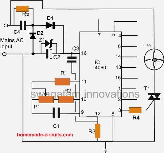
Parts list for the above exhaust fan timer/oscillator circuit
- R1, R3 = 100K
- R2, R4 = 1K
- R5 = 1M
- C1 = 1uF/25V
- C3 = 0.1uF disc
- C2 = 100uF/25V
- C4 = 0.33uF/400V
- Z1 = 15V 1watt zener
- D1, D2 = 1N4007
- T1 = BT136


Comments
Swagatam,
Looks like I am missing something.
Where is D1 in the circuit, and what is its value?
thanks
Sesha
OK, I have corrected the diagram accordingly, please check it now!
Thanks for the quick action.
You have not mentioned D2’s function.
Guess:
D1 “& D2” along with C2, Z1 and C4 forms a ……..?
Yes, you are right, I should have mentioned D2 also. D2 actually allows the C4 capacitor to discharge during each AC half cycles so that the capacitor can deliver the power on the next half cycle. Without D2 the capacitor will charge once and get permanently blocked.
Thanks, please add the above explanation under The Design for all to understand.
Sure! It is done!
Mr Swagatam you have been publishing very intresting circuits with details, very helpful to beginner. thanks a lot. Keep up the good work
Thank you Rajesh! Appreciate your kind words!
Two of my mac97a6 p933 (don’t know its name) wer burned in my Polar stand fan circuit. What is it called? What alternate I can use in the circuit to fix it.
Thanks for your help
It is a triac. You can try BT169.
Hi Swagatam,
I originally requested this circuit. The more useful enhancement will be an asymmetric on off period. This is a binary counter/oscillator so has a symmetric on/off time (equal time off and equal on). Any suggestions for the same?
Hi Anshuman, welcome back! To get an asymmetric control an IC 555 timer could be used, but IC 555 won’t allow us to get precise adjustments. To get an effective control two of these IC4060 circuits could be combined as explained in the following article:
https://www.homemade-circuits.com/how-to-make-simple-programmable-timer/
Thanks Swagatam. Could a simple RC delay on the output suffice (depending on the triggering voltage of the Triac)?
Hi Anshuman, an RC will produce only an initial momentary delay, it won’t oscillate ON/OFF. I think an IC 555 astable could be used since the timing periods are not so crucial.
IC 555 Astable has an issue that the ON time is always larger than the OFF time duration. For this application the ON time will be typically much smaller than the OFF time. Is there a way to invert the output of the Astable mode?
Two BC547 transistor at pin3 will invert the ON/OFF time, or may be a single BC557 will also do the job….
Hai, In the above circuit, The components R5,C2,C4,Z1 converts the 220v AC to 12v DC and gives 12v DC to the circuit. Correct me if I am wrong.
If it is correct means, can I implement that same part of components to other circuits which require 12v DC??
For example, I made a motion activated circuit which consists of one 555 IC and one PIR sensor and I am powering it by a 12v DC adapter. So can I implement the above same connection (parts) to my PIR circuit to avoid the 12v adapter??
anything above 100mA is not recommended through a capacitive power supply…however you can try the following design for acquiring the same, if it works, it would be great.
1uF/400V will provide 70mA…so adding the value will produce proportionately more current.
1000uF will be always a polar capacitor.
1uF/400V is strictly a non-polar
the output will be a DC. although with some ripples.
Some more doubts I have..
1. Suppose if I need 500mA or 1A at output means what should be the C1 (connected parallel to zener z1) value??
2. C2 (1000uf/25v) which is connected parallel to Z1 (zener 15v 1w) is polar and C1(1uf/400v) which connected parallel to R1 is non-polar or polar??
3. At final, The output will be in 12v DC or AC?
It looks OK to me.
C2 = 1000uF/25V
C1 = 0.68uF/400V, if relay does not operate then try 1uF/400V
add a 1N4007 diode right across the zener diode to reduce stress on the zener, polarity same as the zener
amp will be 0.07 or 70mA with a 1uF/400V cap
Thanx. I made a schematic as u said. Check whether it is correct.
imgur.com/srejxTw
and what will be the ampere at the output??
I made R1=1M/ quarter watt,
C2=1000uf/ what volt, polar or non polar?,
Am using a 12v relay at the output, so what should be the C2 value/volt and polar or non polar?,
Z1=15v/1w.
So the output will 12v DC or AC and how much amp at output?
I am going to connect this to circuit to a motion sensor circuit which consists of one PIR, one IC555, and one 12v relay.
Hai, yes it can be done, however C4 will need to be increased if you are using a relay at the output…also preferably C2 should be increased to 1000uF for a better filtration.
with the above circuit you should be extremely careful not to touch the circuit while it's powered since it's not isolated from mains and could produce a lethal electric shock.
ok thanks, i will remove the D1 and see if it will work. if not i will try the 12v ac/dc
good luck to me
OK:)
i follow the diagram but my build wont work..may I ask
1. Theoretically base on the diagram above, what voltage i can measure across?
a. C4
b. C2 or Z1
c. C3
d. pin#16 and pin#8
thanks and regards..really appreciate your answers
C4 voltage is not important.
across C2/Z1 it must be equal to the zener voltage.
C3 is not important
pin16/8 must also show the zener voltage.
you ca replace the C4 power supply by a 12v ac/dc adapter, it would give better results and isolation from lethal mains.
hi again,
im confused , when i first saw this diagram/ckt..there is a D1 even in your design explaination you mention the D1..but right now even how many times refresh this page i cant see the D1 in the diagram/ckt. pls help do clarify. as of this moment im assembling it
Hi, D1 was a mistake, if it's included the circuit won't initiate, so i have removed it.
thank you verymuch..
i find this really an interesting DIY for my exhaust fan..really appreciate if you could share the exact detail of the component of the above circuit.
1. wattage of R1,R2,R3,R4,R5?
.2. type of capacitor for C1, C2, C3, C4?
3. type and value of P1?
thanks in advance
thanks!
all the resistors are 1/4watt 5% CFR
C1,C3,C4 are all metalized polyster type, should NOT be electrolytic.
C2 is electroytic.
P1 could be a 1M or a 500k pot
what is the alternative for c4 0.33microfarad/400V
any other closer value will do.
Thanks Swagatam
Hi Mistral,
Yes you can do the suggested modifications.
for the timing formula you may refer to the following link:
doctronics(dot)co(dot)uk/4060(dot)htm
Hi Swagatam, I am an average hobbyist. I desire to use your circuit to control a larger load say 2KW rated. and I also want mains isolation from the circuit. I propose to power it up using a 12v regulated power supply from a step down transformer and drive a relay that switches the load. Though I may sound like a nerd, I just need to confirm with you if it is ok to feed pin 16 with 12v +ve and use the output from pin 3 to fire the relay circuit using a power transistor and other passive components. Also would be grateful if you can provide a formula for the RC combination to calculate the latching and unlatching time so that I can choose the appropriate values to get a 3hrs on and 3 hrs off time please. Thanks for your time and response.